Advertisement
SERVICE MANUAL
This service manual shows only the differences between
the model WF24T5 and the original model 6424TF.
All other information is described in the service manual
of the model 6424TF.
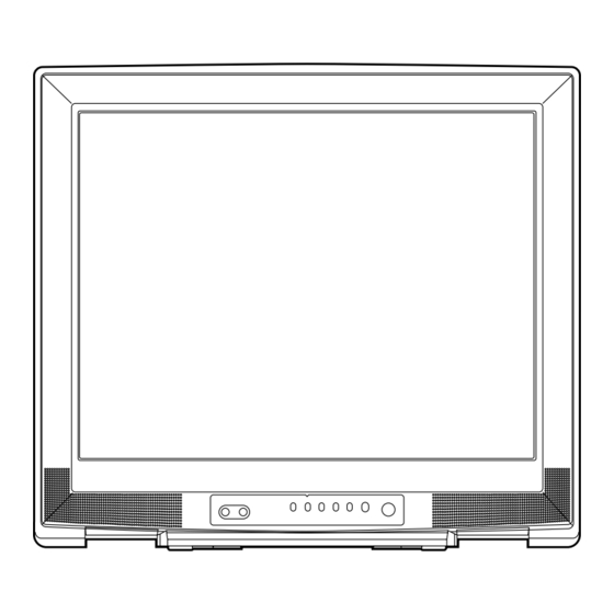
23" COLOR
TELEVISION
WF24T5
Block Diagrams . . . . . . . . . . . . . . . . . . . . . . . . . . . . . . . . . . . . . . . . . . . . . . . . . . . . . . . . . . . . . . . . . .1-1
Schematic Diagrams / Cba's And Test Points . . . . . . . . . . . . . . . . . . . . . . . . . . . . . . . . . . . . . . . . . . .2-1
Different Parts From The Original Model (6424Tf) . . . . . . . . . . . . . . . . . . . . . . . . . . . . . . . . . . . . . . . . .3-1
TABLE OF CONTENTS
SUPPLEMENT
Advertisement
Table of Contents

Summary of Contents for Symphonic WF24T5
- Page 1 SUPPLEMENT SERVICE MANUAL This service manual shows only the differences between the model WF24T5 and the original model 6424TF. All other information is described in the service manual of the model 6424TF. 23″ COLOR TELEVISION WF24T5 TABLE OF CONTENTS Block Diagrams ..............1-1 Schematic Diagrams / CBA’s and Test Points .
- Page 2 BLOCK DIAGRAMS Audio/Power Control Block Diagram L3410BLA...
- Page 3 SCHEMATIC DIAGRAMS / CBA'S AND TEST POINTS Standard Notes Many electrical and mechanical parts in this chassis have special characteristics. These characteristics often pass unnoticed and the protection afforded by them cannot necessarily be obtained by using replacement components rated for higher voltage, wattage, etc. Replacement parts that have these special safety characteristics are identified in this manual and its supplements;...
- Page 4 LIST OF CAUTION, NOTES, AND SYMBOLS USED IN THE SCHEMATIC DIAGRAMS ON THE FOLLOWING PAGES: 1. CAUTION: CAUTION: FOR CONTINUED PROTECTION AGAINST RISK OF FIRE, REPLACE ONLY WITH SAME TYPE_A,_V FUSE. ATTENTION: UTILISER UN FUSIBLE DE RECHANGE DE MÊME TYPE DE_A,_V. 2.
- Page 5 Main 1/3 Schematic Diagram MAIN 1/3 Ref No. Position IC111 IC151 IC801A TRANSISTORS Q111 Q321 Q361 CONNECTOR CN801 L3410SCM1...
- Page 6 Different parts from the original model (6424TF) Ref. No. Description Part No. MECHANICAL PARTS CONTROL PLATE L3410UL 1EM320500 RATING LABEL L3410UL ---------- PB4# CHASISS NO. LABEL L1524V2 ---------- CLOTH(65) L7735TR 65X10X0.5T 0EM402149 CARTON L3410UL 1EM421309 STYROFOAM TOP ASSEMBLY L3400UA 1EM420671 STYROFOAM BOTTOM ASSEMBLY L3400UA 1EM420672 SET SHEET 1150X1900...
- Page 7 WF24T5 L3410UL 2005-06-22...


Need help?
Do you have a question about the WF24T5 and is the answer not in the manual?
Questions and answers