Table of Contents
Advertisement
Quick Links
Advertisement
Table of Contents

Related Manuals for Garnet PC-900G

Summary of Contents for Garnet PC-900G
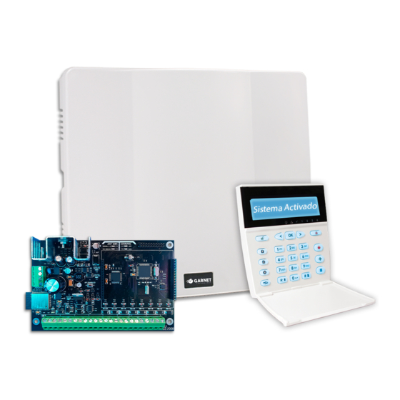
- Page 1 ALARM PANEL Quick programming guide PC-900G ENGLISH...
- Page 2 Expected battery life is a function of the environment, usage and type of device. Environ- mental conditions such as exaggerated humidity, high or low temperatures, or varying WARNING: This manual contains information about the operation of the PC-900G® and its amounts of temperature fluctuations may reduce the life of the battery. Regular testing restrictions, therefore, it should be read carefully.
-
Page 3: Table Of Contents
Section 7: Programming via WiFi......................................13 Technical Specifications......................................... 13 Module Description........................................13 Status light indications........................................13 Programming the communicator and panel from the Garnet Programmer app....................13 Enabling Telephones or Terminals....................................13 Programming videos........................................13 Resetting the communicator configuration to factory defaults..........................13 Section 8: Additional Communicator COM-900 / COM-904...............................14... -
Page 4: Section 1: System Introduction
It is specially designed for the transmission of events via the cellular network. in any of them, obtaining partitions with zones common to 4 partitions. The PC-900G panel has a female pin bed to which the additional COM-900 / COM- Flexible Zone Configuration 904 module is connected and provides an additional communication path. -
Page 5: Additional Devices
WiFi Communicator • DC1 (included via WiFi and Optional via Mobile Networks with COM-900 / COM-904) The embedded WiFi Communicator included in the PC-900G will use a connection • Residential (included via WiFi and optional via mobile networks with COM-900 / via internet to communicate via the various reporting methods. -
Page 6: Section 2: Starting The Installation
FRA-200). cable to the negative. The FRA-200 source is also connected to the BUS-D485 and is fully supervised by the PC-900G® alarm panel. The panel will indicate low battery and mains failure of Transformer terminals: ~AC~ the auxiliary source. -
Page 7: Current Ratings For Modules And Accessories
[+], black to [-], blue to [A] and white to [B]. To connect the zone, use an end-of-line the clock so that the PC-900G® panel can indicate a fault if a module is removed resistor also 2200 ohms between the [Z] terminal and the [-] terminal. To power from the system or simply stops functioning. -
Page 8: Section 3: Keyboard Commands
SECTION 3: Keyboard Commands ][3] Bypass Zones: This command is similar to pressing the [Bypass] key of the Use any system keypad to enter commands and/or program the PC-900G® securi- teclados KPD-860/KPD-860RF/G-LCD732/G-LCD732RF. ty system. [ ][2] Fault Display: The panels constantly monitor the various fault conditions. If a The LCD keypad provides a menu of options on the liquid crystal display and uses fault condition is present, the Fault indicator will flash (see Fault Index Table). -
Page 9: Section 4: How To Program
Communicators. med. If the PC-900G® panel is disarmed before the entry delay expires, an alarm will not be generated. The delay time1 is programmed in the command [151]. -
Page 10: Zone Attributes
Once the keypad zones are installed, assign the zones in programming commands [200]-[207]. NOTE: If the zones assigned to the keypads are between zones 1-8. The same zones on the PC-900G® backplane will override the PC-900G® zones. Bateria 5.7 Download Information The required Download Information software is AC4. -
Page 11: Periodic Test Report
1) The system must report the events to monitoring through the Wifi of the PC-900G board, in the case of not being able to report by IP (Wifi), it will use the mobile data of the chip that has the COM-900 / COM-904 to be able to report to the monitoring station. -
Page 12: Section 6: Programming Wireless Devices
To be sure that a wireless sensor is working properly, the panel has a function that • Allows remote operation of the system via smartphones using the Garnet Control evaluates the Signal Strength Level (RSSI) that the sensor transmits, so that you can App. -
Page 13: Section 7: Programming Via Wifi
In seconds your application will be ready for use To download the programming app, scan the following QR codes as appropriate or NOTE: The Garnet Control application allows up to 20 total users to be associated. search the download shop for the Garnet Programmer app. -
Page 14: Programming Videos
The COM-900 / COM-904 communicator allows the panels to be controlled through 8.5 Communicator programming two methods, one method is through the use of the Garnet Control application, and The programming of the COM-900 / COM-904 communicator is done via the the other method is via text messages or SMS. -
Page 15: Section 9: Reporting Codes Transmitted In Contact Id And Sia
SECTION 9: Reporting Codes Transmitted in Contact ID and SIA Contact ID Type of Event New event or assembly Restoration or Disassembly New Event or Armed Restoration or Disassembly Emergency Medical Key 1 1AA 3 1AA Fire Emergency Key 1 115 3 115 Police Emergency Key 1 12A... -
Page 16: Section 10: Programming Parameters
SECTION 10: Programming parameters Digit position (3): Partition Assignment No. 3 0 = No Control Partition No. 3 1 = Controls Partition No. 3 Command Number 001: Master User Code ( User No. 32 ) Digit position (4): Partition Allocation No. 4 Default values ---------------------------->... - Page 17 Command Number 036: User Code No. 12 Attributes Command Number 050: User Code No. 26 Attributes Default values ---------------------> 1 Default values ----------------------> 1 Positions ----------------------------> (1) Positions ----------------------------> (1) Command Number 037: User Code No. 13 Attributes Command Number 051: User Code No. 27 Attributes Default values ----------------------->...
- Page 18 Command Number 073: Zone No. 4 Configuration Command Number 087: Zone No. 18 Configuration Default values -------------------------------------------------------------------------------> 0 Default values -----------------------------------------------------------------------------> 0 Positions -------------------------------------------------------------------------------------> (1) Positions----------------------------------------------------------------------------------> (1) Command Number 074: Zone No. 5 Configuration Command Number 088: Zone No. 19 Configuration Default values ----------------------------------------------------------------------------->...
- Page 19 Command Number 101: Zone No. 32 Configuration Command Number 118: Zone No. 9 Attributes Default values -----------------------------------------------------------------------------> 0 Default values ----------------------> 1 Positions -------------------------------------------------------------------------------------> (1) Positions -----------------------------> (1) Command Number 110: Zone No. 1 Attributes Command Number 119: Zone No. 10 Attributes Default values ---------------------->...
- Page 20 Command Number 132: Zone No. 23 Attributes Digit position (7): Zone No. 7 Default values ----------------------> 0 = Disabled 1 = Enabled Digit position (8): Zone No. 8 Positions -----------------------------> (1) 0 = Disabled 1 = Enabled Command Number 133: Zone No. 24 Attributes Default values --------------------->...
- Page 21 Command Number 145: Crossing Zones ( 25 to 32 ) Digit position (5): Zone No. 13 0 = Disabled Default values ----------------------> 0 1 = Enabled Digit position (6): Zone No. 14 Positions -----------------------------> (1) 0 = Disabled Digit position (1): Zone No. 25 1 = Enabled 0 = Disabled Digit position (7): Zone No.
- Page 22 Command Number 152: Entry Delay No. 2 Digit positions (1) - (3): Partition Siren Time Default values ----------------------------------------------------> The code must be 3 digits long. Valid values are from 000 to 255 minutes. Command Number 162: Partition No. 4 Siren Time Positions ------------------------------------------------------------------------->...
- Page 23 Command Number 182: PGM-W Configuration No. 1 Default values ----------------------------------------------------------------------------> 0 Positions -------------------------------------------------------------------------> The code must be 3 digits long. Valid values are from 000 to 255 seconds. Positions -------------------------------------------------------------------------------------> (1) Command Number 173: Partition Auto-Arm Timer with Safe Zone/ Digit position (1)- (2): Access Control.
- Page 24 Command Number 193: Partitioning and Keyboard Attribute Assignment No. 4 Default values -----------------------------------------------------------------------------> 0 Default values ----------------------> 1 Positions --------------------------------------------------------------------------------------> (1) Positions -----------------------------> (1) Digit position (1)- (2): Zone No. Assignment to Input No. 1 of Expander Module No. 1 The code must be 2 digits long.
- Page 25 Command Number 232: Zone No. Assign. to Input No. 5 of Expander Module No. 2 Note: If you program 00 the equipment will not monitor the fault. Default values ------------------------------------------------------------------------------> 0 Command Number 245: Auxiliary Fault Counter BUS-D485 Default values ----------------------------------------------------------------------------> 0 Positions ------------------------------------------------------------------------------------->...
- Page 26 Command Number 254: Alarm Counter in Zones Command Number 263: Partitioning Options No. 4 Default values -----------------------------------------------------------------------------> 0 Default values ---------------------> 0 Positions ------------------------------------------------------------------------------------> (1) Positions ------------------------------> (1) Digit position (1)- (2): Alarm Counter in Zones Command Number 270: Panel Options ( I ) The code must be 2 digits long.
- Page 27 Command Number 282: Partition Auto Arming Time No. 3 Command Number 293: Automatic Arming Days for Partition No. 4 Default values ----------------------------> Default values ------------------------------> 0 Positions -------------------------------------------------> Positions ---------------------------------------> (1) Command Number 283: Partition Auto Arming Time No. 4 Command Number 294: Partition No.
- Page 28 Command Number 299: Module Enablement Default Values ----------------------> 0 Positions----------------------------> (1) Digit position (1): Alarm Reporting/Zone Restoration/Police Verification Positions -----------------------------> (1) 0 = Do Not Report 1 = Report Using Scenario No. 1 Digit position (1): Enabling Expander module No. 1 2 = Report Using Scenario No.
- Page 29 Digit position (1): Periodic Test Transmission Counter Digit position (5): Report to monitoring by Wifi Network 0 = Counter in Minutes 0 = Disabled 1 = Counter in Hours 1 = Enabled 2 = Counter in Days Digit position (6): IP-Residential (Reports to App) Digit position (2): Test Transmission Counter Tracker 0 = Disabled 0 = Counter in Minutes...
- Page 30 Command Number 409: Zone Assignment for Wireless Sensor in Memory location Command Number 421: Zone Assignment for Wireless Sensor in Memory location No. 10 No. 22 Default Values ------------------------------------------------------------------------------> 0 Default Values ----------------------------------------------------------------------------> 0 Positions -----------------------------------------------------------------------------------> (1) Positions -----------------------------------------------------------------------------------> (1) Command Number 410: Zone Assignment for Wireless Sensor in Memory location Command Number 422: Zone Assignment for Wireless Sensor in Memory location No.
- Page 31 Command Number 449: Remote Control Functions for Memory location No. 20 Default values -----------------------------------------------> Positions --------------------------------------------------> Command Number 436: Remote Control Functions for Memory location No. 7 Positions --------------------------------------------------> Default values -----------------------------------------------> Command Number 450: Remote Control Functions for Memory location No. 21 Positions -------------------------------------------------->...
- Page 32 Command Number 463: Remote Control Functions for Memory location No. 34 Command Number 477: Remote Control Functions for Memory location No. 48 Default values -----------------------------------------------> Default values -------------------------------------------------> Positions-------------------------------------------------> Positions --------------------------------------------------> Command Number 464: Remote Control Functions for Memory location No. 35 Command Number 478: Remote Control Functions for Memory location No.
- Page 33 Command Number 491: Remote Control Functions for Memory location No. 62 Default values ------------------------------------------------> Positions --------------------------------------------------> Command Number 492: Remote Control Functions for Memory location No. 63 Default values -----------------------------------------------> Positions--------------------------------------------------> Command Number 493: Remote Control Functions for Memory location No. 64 Default values ------------------------------------------------>...
- Page 34 FAULT TABLE (G-LED732/KPD-800) [*][2] Show faults: This command enters the fault display screen. Each general fault is related to a Zone LED. Then, to obtain the fault indication, press the key corresponding to the Zone LED No. indicating the fault. Press Details Indication...
- Page 35 NATIONAL WARRANTY: Alonso Hnos. Sirenas S.A. (Garnet Technology) warrants DISCLAIMER OF WARRANTIES: This warranty contains the entire warranty and to the original purchaser that for a period of 18 months from the date of purchase, shall prevail over all other warranties and all other warranties, whether expressed the product is free from defects in materials and workmanship under normal use.
-
Page 36: Table Of Faults
NOTES... - Page 40 www.garnet.com.ar...
Need help?
Do you have a question about the PC-900G and is the answer not in the manual?
Questions and answers