
Related Manuals for Sport-Tiedje BodyMax Multi Gym MG5


Summary of Contents for Sport-Tiedje BodyMax Multi Gym MG5
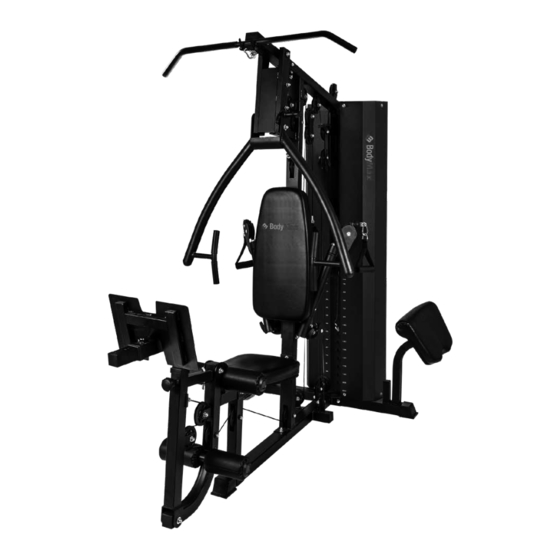
- Page 1 Assembly and Operating Instructions max. 135 kg ~ 400 Min. 195 kg L 187 | B 105 | H 208 SEMG2112.01.01 SKU: SEMG2112 BodyMax Multi Gym MG5...
-
Page 3: Table Of Contents
Content GENERAL INFORMATION Technical Data Personal Safety Set-Up Place ASSEMBLY General Instructions Scope of Delivery Assembly STORAGE AND TRANSPORT General Instructions TROUBLESHOOTING, CARE AND MAINTENANCE General Instructions Faults and Fault Diagnosis Maintenance and Inspection Calendar DISPOSAL RECOMMENDED ACCESSORIES ORDERING SPARE PARTS Serial Number and Model Name Parts List Exploded Drawing... - Page 5 ©2009 BodyMax® is a registered brand of the company Sport -Tiedje GmbH. All rights reserved. Any use of this trademark without the explicit written permission of Sport-Tiedje is prohibited. Product and manual are subject to change. Technical data can be changed without...
- Page 6 ABOUT THIS MANUAL Please carefully read the entire manual before installation and first use. The manual will help you to quickly set up the system and explains how to safely use it. Make sure that all persons exercising with the equipment (especially children and persons with physical, sensory, mental or motor disabilities) are informed about this manual and its contents in advance.
-
Page 7: General Information
GENERAL INFORMATION Technical Data Weight and dimensions: Article weight (gross, incl. packaging): No.1: 62 kg No.2: 15 kg No.3: 28.5 kg No.4: 36.6 kg No.5: 37.5 kg No.6: 37.5 kg Article weight (net, without packaging): 195 kg Packaging dimensions cartons: No.1 (L x W x H): approx. -
Page 8: Personal Safety
Personal Safety ⚠ DANGER Before you start using the equipment, you should consult your physician that this type of exercise is suitable for you from a health perspective. Particularly affected are persons who: have a hereditary disposition to high blood pressure or heart disease, are over the age of 45, smoke, have high cholesterol values, are overweight and/or have not exercised regularly in the past year. -
Page 9: Set-Up Place
Set-Up Place ⚠ WARNING Do not place the equipment in main corridors or escape routes. CAUTION ⚠ Choose a location in which to place the equipment such that there is enough free space/ clearance to the front, the rear and to the sides of the equipment. The training room should be well ventilated during training and not be exposed to any draughts. -
Page 10: Assembly
ASSEMBLY General Instructions ⚠ DANGER Do not leave any tools, packaging materials such as foils or small parts lying around, as otherwise there is a danger of suffocation for children. Keep children away from the equipment during assembly. ⚠ WARNING Pay attention to the instructions attached to the equipment in order to reduce the risk of injuries. -
Page 11: Scope Of Delivery
Scope of Delivery The scope of delivery consist of the following parts. At the beginning, check whether all parts and tools belonging to the device are included in the scope of delivery and whether damage has occurred. In the event of complaints, the contractual partner must be contacted directly. ⚠... -
Page 16: Assembly
Assembly Before assembly, take a close look at the individual assembly steps shown and carry out the assembly in the order given. NOTICE First loosely screw all parts together and check that they fit properly. Tighten the screws using the tool only when you are instructed to do so. If you have difficulty recognising the graphics, we recommend that you open and/or download the PDF instructions stored in the webshop on your end device (e.g. - Page 18 Step 2: Assembly of the Front Stabilizer Assemble the front stabilizer (2) to the rear stabilizer (1) with two connecting brackets (28), two bolts (47), two washers (50) and two nuts (53).
- Page 19 Step 3: Assembly of the Vertical Frame Assemble the vertical frame (3) to the front stabilizer (2) with one long bracket (29), two bolts (48), two washers (50) and two nuts (53).
- Page 20 Step 4: Assembly of the Weight Plates NOTICE The holes of the weight plates need to face the front of the gym. The holes of the weight plates need to point downwards. Slide two rubber bumpers (59) and 14 weight plates (100) through the guide rods (14). Insert the selector rod (1 7) into the weight plates (100).
- Page 21 Step 5: Assembly of the Upper Frame Assemble the upper frame (4) to the guide rods (14) with two bolts (34) and two washers (50). Assemble the upper frame (4) to the vertical frame (3) with two bolts (48), two washers (50), two nuts (53) and one long bracket (29).
- Page 22 Step 6: Assembly of the Seat Support Frame, Slant Support and Backrest Frame Assemble the seat support frame (8) to the front stabilizer (2) with one bolt (47), one washer (50) and one nut (53). Assemble slant support vertical frame with bolts (48), two washers (50), two nuts (53) and one long bracket (29).
- Page 23 Step 7: Assembly of the Front Press Base and Front Press Frame Assemble the front press base (5) to the upper frame (4) with one axle (45), two washers (49) and two nuts (53). Assemble the front press frame (6) to the front press base (5) with one axle (46), two washers (49) and two nuts (53) and secure with the pin (62).
- Page 24 Step 8: Assembly of the Cable Crossover Support and Cable Crossover Arms Assemble the cable crossover support (12) to the vertical frame (3) with two bolts (44), four washers (52) and two nuts (54). Attach the left and right cable crossover arms (20 & 21) to the cable crossover support (12) and secure with two nuts (69) by using the r ound nut hook wrench.
- Page 25 Step 9: Assembly of the Leg Press Platform and the Arm Curl Stand Assemble the front leg developer (9) to the slant support (7) with one axle (43), two washers (49) and two nuts (53). Assemble the leg press support (10) to the front leg developer (9) with one axle (43), two washers (49) and two nuts (53) and secure with L-shaped pin (63).
- Page 26 Step 10: Assembly of the Upper Cable NOTICE If possible: Assemble pulleys and cable simultaneously. Otherwise you can loosely assemble the pulleys first and attach the cable afterwards. Guide the upper cable (96) through the rear opening of the upper frame (4) so the ball end of the cable can’t slip through the opening.
- Page 28 Step 11: Assembly of the Shoulder Cable NOTICE If possible: Assemble pulleys and cable simultaneously. Otherwise you can loosely assemble the pulleys first and attach the cable afterwards. Guide the shoulder cable (98) through the opening of the vertical frame (3) so the ball end of the cable can’t slip through the opening.
- Page 30 Step 12: Assembly of the Crossover Cable NOTICE If possible: Assemble pulleys and cable simultaneously. Otherwise you can loosely assemble the pulleys first and attach the cable afterwards. Guide the crossover cable (99) through the opening of the cable crossover pulley bracket (22), so the ball end of the cable can’t slip through the opening.
- Page 32 Step 13: Assembly of the Low Cable NOTICE If possible: Assemble pulleys and cable simultaneously. Otherwise you can loosely assemble the pulleys first and attach the cable afterwards. Guide the low cable (97) through the opening of the rear stabilizer (1) so the ball end of the cable can’t slip through the opening.
- Page 34 Step 14: Assembly of the Backrest Pad, Seat Pad, Arm Curl Pad and Foams Assemble the arm curl pad (106) to the arm curl stand (13) with two bolts (32) and two washers (51). Assemble the backrest pad (105) to the backrest frame (15) with four bolts (32) and four washers (51).
- Page 35 Step 15: Assembly of the Weight Stack Covers and Foot Pedal Assemble the weight stack covers (25) to the upper frame (4) and rear stabilizer (1) with four bolts (33) and four washers (50). Assemble the foot pedal (19) to the rear stabilizer (1) with the foot pedal axle (31), and secure both ends of the foot pedal with end caps (72).
- Page 36 Step 16: Assembly of the Attachments CAUTION ⚠ Leg exercises can only be made after removing the foot pedal (101) and arm curl stand (13) to avoid serious injury. Attach the short bar (24) to the low cable (97) using one joint chain (67) and two hooks (68). NOTICE When using ankle strap (71) and single strap (70), the short bar (24) must be removed.
-
Page 38: Storage And Transport
STORAGE AND TRANSPORT General Instructions ⚠ WARNING The storage location should be chosen so that improper use by third parties or children can be prevented. If your equipment does not have transportation wheels, the equipment must be disassembled before transportation. ࣑... -
Page 39: Troubleshooting, Care And Maintenance
TROUBLESHOOTING, CARE AND MAINTENANCE General Instructions ⚠ WARNING Do not make any improper changes to the equipment. CAUTION ⚠ Damaged or worn components may affect your safety and the life of the equipment. Therefore, immediately replace damaged or worn components. In such a case, contact the contract partner. -
Page 40: Maintenance And Inspection Calendar
Maintenance and Inspection Calendar To avoid damage from body sweat, the equipment must be cleaned with a damp towel (no solvents!) after each training session. The following routine tasks must be performed at the specified intervals: Part Weekly Monthly Quarterly Cables Screw connections Pulleys and cable routing... -
Page 41: Recommended Accessories
RECOMMENDED ACCESSORIES To make your training experience even more efficient and pleasant, we recommend that you add suiting accessories to your fitness equipment. For training equipment like smith machines, weight benches or racks this could for example be a floor mat, which makes your fitness equipment stand more securely and also protects the floor from sweat but it could be also additional weights, handles, foot straps for leg exercises or triceps ropes. -
Page 42: Ordering Spare Parts
ORDERING SPARE PARTS Serial Number and Model Name In order to provide you with the best possible service, please have the model name, article number, serial number, exploded drawing and parts list ready. The corresponding contact options can be found in chapter 10 of this operating manual. NOTICE The serial number of your equipment is unique. -
Page 43: Parts List
Parts List Name Qty. Name Qty. Rear Stabilizer Allen Bolt (M8*18) Front Stabilizer Allen Bolt (M10*16) Vertical Frame Allen Bolt (M10*20) Upper Frame Allen Bolt (M10*30) Front Press Base Allen Bolt (M10*45) Front Press Frame Allen Bolt (M10*50) Slant Support Pulley Sleeve (L=15) Seat Support Frame Pulley Sleeve (L=25.5) - Page 44 L Shaped Pin (ø10*85*35) Upper Cable (3960mm) T Shaped Pin (M18*1.5*ø12) Low Cable (5200mm) Weight Select Pin Shouler Cable (1880mm) Chain (15 Joints) Cable Crossover Cable (4830mm) Chain (10 Joints) 100 Weight Plate (15LBS) 7# Gourd Hook 101 Upper Plate (10LBS) Aircraft Nut (M24*1.5) 102 Triceps Rope Single Strap...
-
Page 45: Exploded Drawing
Exploded Drawing... -
Page 46: Warranty
WARRANTY Training equipment from BodyMax® is subject to strict quality control. However, if a fitness equipment purchased from us does not work perfectly, we take it very seriously and ask you to contact our customer service as indicated. We are happy to help you by phone via our service hotline. Error Descriptions Your fitness equipment is developed for long-term, high-quality training. - Page 47 Warranty Service Within the warranty period, equipment which develops faults as a result of material or manufacturing defects, will be repaired or replaced at our discretion. Ownership of equipment or parts of equipment which have been replaced is transferred to us. The warranty period is not extended nor does a new warranty period begin following repair or replacement under the warranty.
-
Page 48: Contact
+33 (0) 189 530984 +49 4621 4210-945 +49 4621 42 10 933 �� +49 4621 4210-698 �� �� info@fitshop.dk info@fitshop.fr �� technik@sport-tiedje.de �� �� Åbningstider kan findes på Vous trouverez les heures �� Öffnungszeiten entnehmen Sie hjemmesiden. d’ouverture sur notre site unserer Homepage. - Page 49 70 stores and one of the world’s most renowned online mail order companies for fitness equipment. https://www.facebook.com/powerhousefitness.co.uk Powerhouse Fitness is part of the Sport-Tiedje Group. Private customers order via the 25 web shops in the respective national language or have their desired equpiment assembled on www.instagram.com/powerhousefitness_uk/...
- Page 50 Notes...
- Page 52 BodyMax Multi Gym MG5...
Need help?
Do you have a question about the BodyMax Multi Gym MG5 and is the answer not in the manual?
Questions and answers