
Summary of Contents for REO REOVIB MFS 368
- Page 1 □ REOVIB Control units for vibratory conveyor technology MFS 368 Frequency converter for vibratory feeders MFS368_ANL_rev01.en.doc 18.08.2023...
-
Page 2: Table Of Contents
REOVIB MFS 368 Operating instructions Table of contents Safety instructions for the user ........................3 Declaration of Conformity ..........................6 Changes / Copyright ............................. 6 1.0 General ..............................7 2.0 Function ..............................7 2.1 Track control ............................8 2.2 Operation with two speeds (2 setpoint for coarse/fine switching) ............ -
Page 3: Safety Instructions For The User
Safety instructions for the user IMPORTANT! READ CAREFULLY BEFORE USE AND KEEP FOR FUTURE REFERENCE! This description contains the information required for correct use of the products described in it. It is intended for technically qualified personnel. Qualified personnel are persons who, because of their training, experience and instruction, as well as their knowledge of applicable standards, regulations, health and safety requirements and operating conditions, have been authorized by those responsible for the safety of the equipment to carry out required activities at any time, and who can recognize and avoid possible hazards in the course of these... - Page 4 REOVIB MFS 368 Operating instructions WARNING Electric shock if the cable shield is not connected Capacitive coupling can cause life-threatening touch voltages if the cable shields are not connected. Connect cable shields and unused cores of power lines to earthed housing potential on at least one side.
- Page 5 REOVIB MFS 368 Operating instructions WARNING Influence of electromagnetic fields on active implants Frequency converters generate electromagnetic fields (EMF) during operation. Electromagnetic fields can affect active implants, e.g. pacemakers. This puts people with active implants in the immediate vicinity of an frequency converter at risk.
-
Page 6: Declaration Of Conformity
Changes / Copyright We reserve the right to make changes to the technical design and documentation without prior notice. REO AG reserves the copyright to these instructions. Reproduction, computerisation and filming of any kind is not permitted without written consent. -
Page 7: General
REOVIB MFS 368 Operating instructions 1.0 General The control unit generates an adjustable output frequency for the vibratory feeder independently of the mains frequency. The PFC circuit on the input side ensures a constant output voltage both at an input voltage of 110 V and 230 V. -
Page 8: Track Control
REOVIB MFS 368 Operating instructions whether parts pass the sensor within a period of time (e.g. no-load signal). As an alternative to the material flow control, the sensor input can be used for switching to a second, internally adjustable setpoint, e.g. to realise a "fast/slow" function. In parallel with control of the feeder, a 24 V DC output is available for the IP54 housing version, which can control a blowing air valve to support the parts flow. -
Page 9: Enable Input
REOVIB MFS 368 Operating instructions 2.3 Control inputs and outputs 2.3.1 Enable input Potential-free contact or 24 VDC signal. External control option for switching the power output On/Off, e.g. for linking several units or control by a PLC. 2.3.2 Sensor input for track control Sensor for monitoring the material level in a backlog section or input for switching to a second setpoint. -
Page 10: Touch Panel
REOVIB MFS 368 Operating instructions 2.4 Touch panel The units are operated via the operating keys and the text/graphic display. bols "Fun ction " Conveying capacity Feeder Locked no enable Track Ctrl. Limits Information Language Operating display Time out Status line : 90.0 %... -
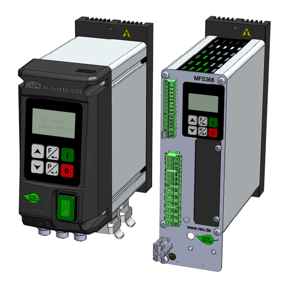
Page 11: Structure
REOVIB MFS 368 Operating instructions 3.0 Structure The unit is available as IP54 or IP 20 version. 3.1 IP54 • Power switch • Control and display panel • Mains supply lead (optional) • Output cable or output socket for feeder connection •... -
Page 12: Load Supply Requirements
REOVIB MFS 368 Operating instructions 4.1 Load supply requirements The unit is not suitable for feeder coils with a power of <18 VA (100 mA). 4.2 Terminal details Tightening torque: Terminals MSTB/GMSTB, GMSTB-GIC: 0.5-0.6 Nm Connections: 21-29 and 44-46 MC terminals: 0.22-0.25 Nm... -
Page 13: Ordering Code (Standard Units)
REOVIB MFS 368 Operating instructions 5.0 Ordering code (Standard units) 6368 0= --- 1= EC 2= E I/P 3= PN 4= DP 5= CAN 6= DN 1= 3 A 2= 6 A 3= 8 A 0= IP20 V 1= IP20 V UL... -
Page 14: Possible Settings
REOVIB MFS 368 Operating instructions 6.0 Possible settings Icon Menu item Meaning Setting Factory setting Output Feeder Feed rate 0...100% Setpoint "Fine" (previously "Activate 1.1.1 Fine 0...100% coarse / fine") Feeder Frequency Set frequency 35...140 Hz 100 Hz Invert Enable... - Page 15 REOVIB MFS 368 Operating instructions Info Software version Service Clear ERROR & Clear ERROR & reset execute reset Factory settings* Load factory settings execute Parameter set Select parameter set 1 / 2 / 3 / 4 Save current parameters in the Save parameters selected parameter set (only if key no.
-
Page 16: Operating Elements
REOVIB MFS 368 Operating instructions 7.0 Operating elements Abort, Exit Start / Reset Select menu / parameter, Adjust value Stop Confirm, Apply, Select menu 7.1 Setting behaviour Start on the Homescreen Jumping to the menu from the home screen Navigate to the desired menu item... -
Page 17: Parameter Setting Example
REOVIB MFS 368 Operating instructions 7.1.1 Parameter setting example Black background : Men / arameter selected Operating mode Power Power Power Feeder Feeder 10.0% Feeder 10.0% : 90.0 % Frequency: 50,5 Hz Track Ctrl. Limits Power Power Power Feeder 10.0% Feeder 20.0%... -
Page 18: Commissioning
REOVIB MFS 368 Operating instructions 8.0 Commissioning 8.1 Preparatory measures Notes With the control units described here, it is possible to adjust the resonant frequency of the connected feeder. Since in this case even a small setpoint value can lead to full operation of the feeder, appropriate care must be taken to ensure that no damage occurs in the feeder due to coil hammering. -
Page 19: Settings
REOVIB MFS 368 Operating instructions 9.0 Settings 9.1 Notes on controller mode • For controller mode, an accelerometer mounted on the vibratory feeder is required, e.g. SW 70 (for IP54 units) or SW10 (for IP20 units). • In control mode with sensor feedback, all vibrations detected by the sensor are processed in the control circuit. - Page 20 REOVIB MFS 368 Operating instructions In the case of bowl feeders, it is advisable to mount the sensor as far as possible on the outer diameter so that the largest possible vibration displacement is covered. If the sensor signal is too low, the setpoint's control range is significantly restricted.
-
Page 21: Correlation Between Acceleration And Vibration Amplitude
REOVIB MFS 368 Operating instructions 9.3 Correlation between acceleration and vibration amplitude The sensor measures the feeder's instantaneous acceleration. This results in a sinusoidal output voltage of the sensor. The acceleration increases with increasing vibrating frequency. Therefore, the sensor output signal can be larger at high frequencies and small vibration amplitude than at low frequencies and larger vibration amplitude. -
Page 22: Commissioning The Control Unit In Control Mode
REOVIB MFS 368 Operating instructions 9.5 Commissioning the control unit in control mode Connect the control unit Mount and connect the sensor Automatic frequency search and controller mode Initial commissioning using the example of a 50 Hz feeder: Procedure Adjustment menu and... -
Page 23: Troubleshooting
REOVIB MFS 368 Operating instructions 10.0 Troubleshooting Error messages If there is an error, a message flashes in the first line of the display. Error_2401/2402 Acc sensor fault: Acc. sensor not connected, or defective. Error_0005 Overvoltage: Mains input voltage too high. -
Page 24: Housing Version Connection
REOVIB MFS 368 Operating instructions 11.0 Housing version connection Internal connection 3...8 A units Input External setpoint +10V/DC Thermal switch connection (Series) Ferrite sleeve L,N,PE / 50/60Hz Different connection options are available depending on the unit design. Plug and Vib (PV) version:... -
Page 25: Connection Of Control Cabinet Version
REOVIB MFS 368 Operating instructions 12.0 Connection of control cabinet version Trackcontrol sensor Input +24V/DC Input Enable +24V/DC External setpoint Input +10V/DC (Black) GND (Orange) Input ACC-Sensor (Red) +24V/DC Shielding Input Thermal switch connection +24V/DC (Series) Status relay Ready relay... - Page 26 REOVIB MFS 368 Operating instructions external enable Voltage Potential free without external enable: +24V/DC Contact Use a bridge external setpoint Potentiometer Control voltage / Control current (switchable in menu: "Feeder") 10 kΩ...
-
Page 27: Dimension Drawing
REOVIB MFS 368 Operating instructions 13.0 Dimension drawing Housing versions 47,5 47,5... - Page 28 REOVIB MFS 368 Operating instructions Installation clearances...
- Page 29 REOVIB MFS 368 Operating instructions Control cabinet version Installation clearances All dimensions in [mm]...
-
Page 30: Assembly Instruction
REOVIB MFS 368 Operating instructions 14.0 Assembly instruction Only suitable for mounting on concrete or other non-combustible surfaces. -
Page 31: A 1.0 Accessories / Options
REOVIB MFS 368 Operating instructions A 1.0 Accessories / Options Product Ordering number Ferrite sleeve for output cable 221800000000600 Plug-in output cable with ferrite sleeve 900090359 Shield connection terminal KLBUE 3-8 SC 27100190100 REOVIB MEASUREMENT BOX 10A IP40 300V 20001220101... - Page 32 Divisions: India REO GPD INDUCTIVE COMPONENTS PVT. LTD E-Mail: info@reogpd.com · Internet: www.reo-ag.in REO Vibratory Feeding and Power Electronics Division Brühler Straße 100 · D-42657 Solingen Tel.: +49 (0)212 8804 0 · Fax: +49 (0)212 8804 188 REO-USA, Inc. E-Mail: info@reo.de E-Mail: info@reo-usa.com ·...
Need help?
Do you have a question about the REOVIB MFS 368 and is the answer not in the manual?
Questions and answers