Table of Contents
Advertisement
Contents
Chapter 1. About this manual ................................................ 1
Chapter 2. Safety information ................................................ 4
Chapter 3. General information ...........................................12
Chapter 4. General Checkout ...............................................13
Chapter 5. Using the Setup Utility (Type G43) .................16
Important Safety Information ...................................................................... 1
Using eSupport .................................................................................................... 2
General safety ....................................................................................................... 4
Electrical safety .................................................................................................... 5
Safety inspection guide ................................................................................... 7
Handling electrostatic discharge-sensitive devices ......................... 8
Grounding requirements ............................................................................... 8
Safety notices ........................................................................................................ 9
Specifications ..................................................................................................... 12
Problem determination tips ...................................................................... 14
Starting the Setup Utility program ......................................................... 16
Viewing and changing settings ................................................................ 16
Using passwords .............................................................................................. 17
Using Device ...................................................................................................... 19
Selecting a startup device ........................................................................... 20
Exiting from the Setup Utility program ................................................ 21
Contents
i
Advertisement
Table of Contents

Related Manuals for Lenovo IdeaCentre A320


Summary of Contents for Lenovo IdeaCentre A320
-
Page 1: Table Of Contents
Contents Chapter 1. About this manual ... 1 Important Safety Information ... 1 Using eSupport ... 2 Important information about replacing RoHS compliant FRUs .. 2 Chapter 2. Safety information ... 4 General safety ... 4 Electrical safety ... 5 Safety inspection guide ... - Page 2 Hardware Maintenance Manual Chapter 6. Symptom-to-FRU Index...22 Hard disk drive boot error ... 22 Power Supply Problems ... 23 Beep symptoms ... 24 POST error codes ... 25 Undetermined problems ... 27 Chapter 7. Replacing hardware ...28 General information ... 28 Removing the computer cover ...
-
Page 3: Chapter 1. About This Manual
IdeaCentre K computers listed on the cover. It is intended only for trained servicers who are familiar with Lenovo computer products. Before servicing a Lenovo product, be sure to read the Safety Information. This manual includes a complete FRU part number listing for each machine type and model listed on the cover. -
Page 4: Using Esupport
Electronic Equipment Directive (2002/95/EC) is a European Union legal requirement affecting the global electronics industry. RoHS requirements must be implemented on Lenovo products placed on the market after June 2006. Products on the market before June 2006 are not required to have RoHS compliant parts. - Page 5 Lenovo’s requirements and schedule. Products sold in 2005, will contain some RoHS compliant FRUs. The following statement pertains to these products and any product Lenovo produces containing RoHS compliant parts.
-
Page 6: Chapter 2. Safety Information
Hardware Maintenance Manual Safety information This chapter contains the safety information that you need to be familiar with before servicing a computer. General safety Follow these rules to ensure general safety: • Observe good housekeeping in the area of the machines during and after maintenance. -
Page 7: Electrical Safety
• Wear safety glasses when you are: hammering, drilling soldering, cutting wire, attaching springs, using solvents, or working in any other conditions that might be hazardous to your eyes. • After service, reinstall all safety shields, guards, labels, and ground wires. Replace any safety device that is worn or defective. - Page 8 Hardware Maintenance Manual • If you need to work on a machine that has exposed electrical circuits, observe the following precautions: – Ensure that another person, familiar with the power-off controls, is near you. Remember: Another person must be there to switch off the power, if necessary.
-
Page 9: Safety Inspection Guide
Safety inspection guide The intent of this inspection guide is to assist you in identifying potentially unsafe conditions on these products. Each machine, as it was designed and built, had required safety items installed to protect users and service personnel from injury. This guide addresses only those items. However, good judgment should be used to identify potential safety hazards due to attachment of features or options not covered by this inspection guide. -
Page 10: Handling Electrostatic Discharge-Sensitive Devices
Hardware Maintenance Manual Handling electrostatic discharge-sensitive devices Any computer part containing transistors or integrated circuits (ICs) should be considered sensitive to electrostatic discharge (ESD). ESD damage can occur when there is a difference in charge between objects. Protect against ESD damage by equalizing the charge so that the machine, the part, the work mat, and the person handling the part are all at the same charge. -
Page 11: Safety Notices
Safety notices The caution and danger safety notices in this section are provided in the the language of English. DANGER Electrical current from power, telephone and communication cables is hazardous. To avoid a shock hazard: • Do not connect or disconnect any cables or perform installation, maintenance, or reconfiguration of this product during an electrical storm. - Page 12 Hardware Maintenance Manual CAUTION: When replacing the lithium battery, use only Part Number 33F8354 or an equivalent type battery recommended by the manufacturer. If your system has a module containing a lithium battery, replace it only with the same module type made by the same manufacturer. The battery contains lithium and can explode if not properly used, handled, or disposed of.
- Page 13 Chapter 2. Safety information CAUTION: Use safe practices when lifting. CAUTION: The power control button on the device and the power switch on the power supply do not turn off the electrical current supplied to the device. The device also might have more than one power cord. To remove all electrical current from the device, ensure that all power cords are disconnected from the power source.
-
Page 14: Chapter 3. General Information
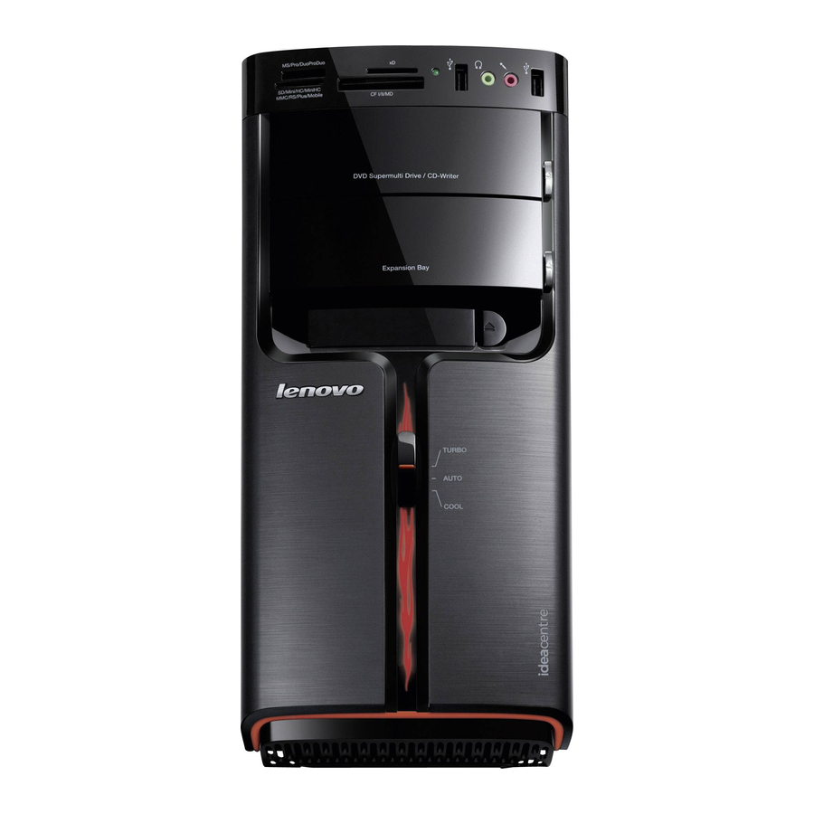
Hardware Maintenance Manual General information This chapter provides general information that applies to all machine types supported by this publication. Specifications This section lists the physical specifications for your computer. Type IdeaCentre K3 This section lists the physical specifications. Dimensions Environment Electrical input Width: 180 mm... -
Page 15: Chapter 4. General Checkout
General Checkout Attention The drives in the computer you are servicing might have been rearranged or the drive startup sequence changed. Be extremely careful during write operations such as copying, saving, or formatting. Data or programs can be overwritten if you select an incorrect drive. -
Page 16: Problem Determination Tips
Hardware Maintenance Manual 5. Power-on the computer. • Look for displayed error codes • Listen for beep codes • Look for readable instructions or a main menu on the display. If you did not receive the correct response, proceed to step 6. If you do receive the correct response, proceed to step 7. 6. Look at the following conditions and follow the instructions: •... - Page 17 Chapter 4. General Checkout Comparing the configuration and software set-up between “working and non-working” systems will often lead to problem resolution.
-
Page 18: Chapter 5. Using The Setup Utility (Type G43)
Hardware Maintenance Manual Using the Setup Utility (Type G43) The Setup Utility program is used to view and change the configuration settings of your computer, regardless of which operating system you are using. However, the operating-system settings might override any similar settings in the Setup Utility program. -
Page 19: Using Passwords
keyboard. The keys used to perform various tasks are displayed on the right side of each screen. Using passwords By using the Setup Utility program, you can set passwords to prevent unauthorized persons from gaining access to your computer and data. See “Starting the Setup Utility program. -
Page 20: Setting, Changing, And Deleting A Administrator Password
Hardware Maintenance Manual Setting, changing, and deleting a Administrator password To set, change, or delete a password, do the following: Note: A password can be any combination of up to 16 characters (A- Z, a-z, 1. Start the Setup Utility program (see “Starting the Setup Utility program” on page 16). -
Page 21: Using Device
2. From the Setup Utility program menu, Select Security. 3. selet Change User Password and press Enter. 4. Select Set Power-On Password and press Enter. 5. when prompted to confirm the password, type the password again. If you type the password correctly, the password will be installed. To delete a previously set power-on password, do the following : Note: When prompted for a password, you must type your administrator 1. -
Page 22: Selecting A Startup Device
Hardware Maintenance Manual Selecting a startup device If your computer does not start up (boot) from a device such as the CD-ROM, diskette, or hard disk as expected, use one of the following procedures to select a startup device. Selecting a temporary startup device Use this procedure to startup from any boot device. -
Page 23: Exiting From The Setup Utility Program
Chapter 5. Using the Setup Utility Exiting from the Setup Utility program When you finish viewing or changing settings, press Esc to return to the Setup Utility program menu (you might have to press Esc several times). If you want to save the new settings, select Save changes and Exit before you exit. -
Page 24: Hardware Maintenance Manual
Hardware Maintenance Manual Symptom-to-FRU Index The Symptom-to-FRU index lists error symptoms and possible causes. The most likely cause is listed first. Always begin with Chapter 4, “General Checkout, ” on page 13. This index can also be used to help you decide which FRUs to have available when servicing a computer. -
Page 25: Power Supply Problems
Error The boot sector on the start-up drive is corrupted. The drive is defective. Power Supply Problems If you suspect a power problem, use the following procedures. Check/Verify Check the following for proper installation. • Power Cord • On/Off Switch connector •... -
Page 26: Beep Symptoms
Hardware Maintenance Manual Beep symptoms Beep symptoms are tones or a series of tones separated by pauses (intervals without sound) during POST. The following tables describes beep symptoms. Beep Symptom 1 beep Memory refresh timer error 2 beeps Parity error in base memory (first 64KB block) 3 beeps Base memory read/write test error... -
Page 27: Post Error Codes
Beep Symptom 9 beeps AMIBIOS ROM checksum error 10 beeps CMOS shutdown register read/write error 11 beeps Cache memory test failed POST error codes Each time you power-on the system, it performs a series of tests that check the operation of the system and some options. This series of tests is called the Power-On Self-Test, or POST. - Page 28 Hardware Maintenance Manual POST Error Message CMOS Date/Time Not Set CMOS Battery Low CMOS Checksum Bad Primary Master Hard Disk Error Primary Slave Hard Disk Error Secondary Master Hard Disk Error Secondary Slave Hard Disk Error PS2 Mouse not found Keyboard error System Haulted Press TAB to show POST screen...
-
Page 29: Undetermined Problems
POST Error Message Reboot and Select proper Boot device or Insert Boot Media in selected Boot device Undetermined problems If this computer has a parallel ATA hard disk drive, make sure that the hard disk drive is jumpered as a master and the optical drive is jumpered as a slave. -
Page 30: Chapter 7. Replacing Hardware
Maintenance Manual (HMM) for the computer. To obtain copies of the Safety and Warranty Guide or HMM, go to the Support Web site at http://consumersupport.lenovo.com Note Use only parts provided by Lenovo. General information Pre-disassembly instructions Before proceeding with the disassembly procedure, make sure that you do the following: 1. -
Page 31: Removing The Computer Cover
Removing the computer cover Attention Turn off the computer and wait 3 to 5 minutes to let the computer cool before removing the computer cover. To remove the computer cover: 1. Remove any media (diskettes, CDs, or memory cards) from the drives, shut down your operating system, turn off all attached devices, and the computer. -
Page 32: Removing The Front Bezel
Hardware Maintenance Manual Removing the front bezel To remove the front bezel: 1. Remove the computer cover. Refer to “Removing the computer cover”. Note For this procedure, it helps to lay the computer on its side. 2. Remove the front bezel by releasing the three plastic tabs inside the chassis and push the bezel outward as shown. -
Page 33: Replacing A Memory Module
Guide that was included with your computer or in the Hardware Maintenance Manual (HMM) for the computer. To obtain copies of the Safety and Warranty Guide or HMM, go to the Support Web site at http://consumersupport.lenovo.com Chapter 7. Replacing hardware... - Page 34 Hardware Maintenance Manual To replace a memory module: 1. Remove the computer cover. Refer to “Removing the computer cover”. Note For this procedure, it helps to lay the computer on its side. 2. Locate the memory module connectors. Refer to “Locating components”.
-
Page 35: Replacing The Hard Disk Drive
Maintenance Manual (HMM) for the computer. To obtain copies of the Safety and Warranty Guide or HMM, go to the Support Web site at http://consumersupport.lenovo.com To replace the hard disk drive: 1. Remove the computer cover. Refer to “Removing the computer cover”. -
Page 36: Replacing An Optical Drive
Maintenance Manual (HMM) for the computer. To obtain copies of the Safety and Warranty Guide or HMM, go to the Support Web site at http://consumersupport.lenovo.com To replace an optical drive 1. Remove the computer cover. Refer to “Removing the computer cover”. -
Page 37: Replacing The System Fan Assembly
Guide that was included with your computer or in the Hardware Maintenance Manual (HMM) for the computer. To obtain copies of the Safety and Warranty Guide or HMM, go to the Support Web site at http://consumersupport.lenovo.com Chapter 7. Replacing hardware... - Page 38 Hardware Maintenance Manual To replace the system fan assembly: 1. Remove the computer cover. Refer to “Removing the computer cover”. 2. Locate the system fan assembly. Refer to “Identifying parts on the system board”. 3. Disconnect the system fan assembly cable from the system board. Refer to“Identifying parts on the system board”.
- Page 39 5. Install the new system fan assembly by aligning the rubber mounts of the system fan assembly with the holes on the chassis and push the rubber mounts through the holes. 6. Pull on the tips of the rubber mounts until the fan assembly is in place. 7.
-
Page 40: Replacing The Heat Sink Assembly
Maintenance Manual (HMM) for the computer. To obtain copies of the Safety and Warranty Guide or HMM, go to the Support Web site at http://consumersupport.lenovo.com To replace the heat sink assembly: 1. Remove the computer cover. Refer to “Removing the computer cover”. -
Page 41: Replacing A Pci Or Agp Adapter
Maintenance Manual (HMM) for the computer. To obtain copies of the Safety and Warranty Guide or HMM, go to the Support Web site at http://consumersupport.lenovo.com To replace an adapter: 1. Remove the computer cover. Refer to “Removing the computer cover”. - Page 42 Hardware Maintenance Manual 2. At the rear of the computer, press the release button adapter latch the adapter connector. and remove the adapter by pulling it straight out of to open the...
- Page 43 Chapter 7. Replacing hardware 3. Install the new adapter into the same adapter connector. 4. Ensure the adapter is fully seated into the adapter connector. 5. At the rear of the computer, pivot the adapter latch to the closed position to secure the adapter. 6.
- Page 44 Hardware Maintenance Manual Note 1 eplacement of some models equipped with graphic adapter bracket is different. Please remove the plastic bracket first as the following: 1. Remove the two screws that secure the plastic bracket at the bottom of the chassis. 2.
- Page 45 2. Install the two screws to secure the plastic bracket. Note Use only the screws provided by Lenovo. Note 2 Replacement of some models equipped with graphic adapter bracket is different. Please remove the bracket first as the following: 1. Remove the screw that secures the bracket at the side of the chassis.
- Page 46 Hardware Maintenance Manual 2. Press the pin on one end of the metal bracket and pull the metal bracket straight out of the chassis. After the Graphic Adapter is installed, install the bracket as the following: 1. Install the metal bracket into the chassis so that the screw hole in the metal bracket aligns with the hole in the chassis.
-
Page 47: Replacing The Cpu
2. Screw back the screws on the metal bracket. Note Use only the screws provided by Lenovo. Replacing the CPU Attention Do not remove the computer cover or attempt any repair before reading the “Important safety information” in the Safety and Warranty Guide that was included with your computer or in the Hardware Maintenance Manual (HMM) for the computer. - Page 48 Hardware Maintenance Manual To replace an CPU 1. Remove the computer cover. Refer to “Removing the computer cover”. 2. Remove the front bezel. Refer to “Removing the front bezel”. 3. Remove the system board. Refer to “Replacing the heat sink assembly”. 4.
- Page 49 Note a. Note the orientation of the notches This is important when reinstalling the microprocessor on the new system board. b. Do not drop anything onto the microprocessor socket while it is exposed. The socket pins must be kept as clean as possible. 7.
- Page 50 Hardware Maintenance Manual Important To avoid damaging the microprocessor contacts, do not tilt the microprocessor when installing it into the socket. 10. Lower the microprocessor straight down into the system board socket of the system board. 11. To secure the microprocessor in the socket, close the microprocessor retainer and lock it into position with the small handle.
-
Page 51: Replacing The Keyboard
Replacing the keyboard To replace the keyboard: 1. Remove any media (diskettes, CDs, or memory cards) from the drives, shut down your operating system, and turn off all attached devices and the computer. 2. Unplug all power cords from electrical outlets. 3. -
Page 52: Replacing The External Speaker
Hardware Maintenance Manual Note Your mouse might be connected to the standard mouse connector at the rear of the computer or to a USB connector front or rear of the computer. 4. Disconnect the failing mouse cable from the computer. 5. -
Page 53: Completing The Installation
4. Disconnect the failing speaker cable from the computer and connect the new speaker cable to the same connector. Completing the installation After replacing the parts, you need to close the computer cover and reconnect cables, including telephone lines and power cords. Also, depending on the part that was replaced, you might need to confirm the updated information in the Setup Utility program. - Page 54 Utility” in the User Guide or in the Hardware Maintenance Manual. Note In most areas of the world, Lenovo requires the return of the defective CRU. Information about this will come with the CRU or will come a few days after the CRU arrives.
-
Page 55: Chapter 8. Additional Service Information(Type G43)
Additional Service Information (Type G43) This chapter provides additional information that the service representative might find helpful. Power management Power management reduces the power consumption of certain components of the computer such as the system power supply, processor, hard disk drives, and some monitors. Automatic configuration and power interface (ACPI) BIOS Being an ACPI BIOS system, the operating system is allowed to control... - Page 56 Thanks for using Lenovo products. Carefully read all of the documents shipped with your computer before you install and use the product for the first time. Lenovo will not assume responsibility for damage that results from failure to operate the product according to instructions and requirements described in the manuals included with your computer.
-
Page 57: Appendix. Statement
Advanced Micro Devices, Inc. in the United States and/or other jurisdictions. The table above includes the logo and registered trademarks of Lenovo and its partners. Other registered trademarks mentioned in all the manuals included with your computer belong to the specific company respectively.
Need help?
Do you have a question about the IdeaCentre A320 and is the answer not in the manual?
Questions and answers