Table of Contents
Advertisement
Quick Links
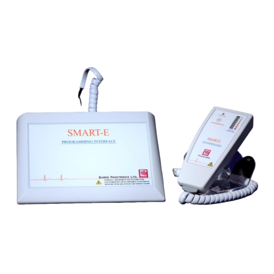
SMART – E
Programming Interface
Model: SEP – 11
Programming Head
Model: SEH – 11
Shree Pacetronix Ltd.
Plot No. 15, Sector II,
Industrial Area,
Pithampur, Dist. Dhar
454775 (M.P.), INDIA
Telephone: 07292-411105
Fax: 07292-2762728
E-mail:
pacetronix@hotmail.com
Website:
http://www.pacetronix.com
PROGRAMMER
USER MANUAL
Advertisement
Table of Contents

Summary of Contents for Pacetronix SMART-E PROGRAMMER
- Page 1 SMART – E PROGRAMMER USER MANUAL Programming Interface Model: SEP – 11 Programming Head Model: SEH – 11 Shree Pacetronix Ltd. Plot No. 15, Sector II, Industrial Area, Pithampur, Dist. Dhar 454775 (M.P.), INDIA Telephone: 07292-411105 Fax: 07292-2762728 E-mail: pacetronix@hotmail.com Website: http://www.pacetronix.com...
- Page 2 Revision Date Change Description January 15 , 2017 August 25 , 2020 User Information...
- Page 3 Explanation of Symbols Serial Symbol Symbol Explanation Number Operating instructions Do not dispose of this product in the unsorted municipal waste stream. Dispose of this product according to local regulations Product documentation DEFIBRILLATION-PROOF TYPE BF APPLIED PART. General warning sign...
-
Page 4: Table Of Contents
Contents 1. MANUAL CONTAINS ................. 5 2. GENERAL ..................... 7 3. INTRODUCTION ..................9 4. TECHNICAL SERVICE ................9 5. CONNECTORS AND INDICATORS DESCRIPTION ......10 Connections of Programming Interface ..........10 Indicators on SMART-E Programming Head Model SEH-11 ....11 6. - Page 5 11. CLEANING ....................31 12. SAFETY & TECHNICAL CHECKS ............32...
-
Page 6: Manual Contains
1. MANUAL CONTAINS This manual explains the use of the SMART-E programmer for Pacemaker Model SEP- 11 with SPL software. It is divided in the following sections: Introduction In this first section, the basic requirements, Connections, indications and the SPL software installation procedure are described. -
Page 8: General
SEH-11, USB cable & ECG cable. Programmer is a device used for programming of the pacemaker with the help of PC/Laptop. SMART-E Programmer Model SEP-11 is connected by means of an interface to a laptop/PC, which communicates by telemetry to the pacemaker implanted in the patient. - Page 9 Company will replace all components and provide service free of charge. 2. Limitation of Liability, Shree Pacetronix Ltd. shall not be liable for any medical expenses, adverse body reactions, or medical complications or other direct or...
-
Page 10: Introduction
4. TECHNICAL SERVICE ln case of additional help about SMART-E Programmer Model SEP-11, SPL software or about SSI / SSIR / DDD / DDDR / Bi-Ventricular pacemaker series you may consult Pacetronix through: Mail: Plot No.15, Sector-II, Pithampur, Dist. -
Page 11: Connectors And Indicators Description
USB Cable Connection: • To PC Connect USB cable PC end to USB port of the PC to connect programming interface with the PC to powering up the SMART-E Programmer Model SEP- 11 system. • To SMART-E Programmer Model SEP-11 Connect USB cable Interface end to programming interface female connector USB I/O. -
Page 12: Indicators On Smart-E Programming Head Model Seh-11
Power-up indicator Power-up indicator is placed on the SMART-E Programming Head Model SEH-11. When SMART-E Programmer Model SEP-11 powered-up by USB port of the PC, a green LED on LED bar glows, and indicating power-up of SMART-E Programmer Model SEP-11. -
Page 13: System Requirements
Double click the ” setup “ file in the folder. Once the Auto Run Installation program begins just follow the instructions. The notebooks supplied by Pacetronix have SPL software preinstalled; in this case the installation is not necessary. 7. INSTRUCTION FOR USE 1. -
Page 14: Spl Software Screen
6. Now place SMART-E Programming Head Model SEH-11 on to implantable device (Pacemaker) site on the patient. 7. Please ensure that LED’s are blinking on LED bar on the SMART-E Programming Head Model SEH-11. 8. For proper telemetry ensure that green LED’s should blink. The SMART-E Programming Head Model SEH-11 must be placed over the implant zone, making sure that the light blinks following its frequency. -
Page 15: Run Spl Software
In some cases, the actions executed using the mouse, can also be carried out using the keyboard by pressing different keys combinations called keyboard shortcuts. For example: when the computer is turned on, a screen called Windows XP / 98 Desktop, in which the Start button is seen in the left lower part, appears. - Page 16 Reduces the maximized window to a minor size. In this status the window can be moved throughout the screen (dragging it from the title bar) and its size can be modified (moving the pointer up to the borders until it becomes a double arrow, and dragging it).
- Page 17 Statistics button: it allows reading the statistic values stored by the pacemaker, such as stimulus generated, sensed events, etc. The information is shown in absolute numbers, in percentages, or by means of bar graphics. Impedance button: This button allows measuring the lead impedance. Longitivity calculation of pacemaker at different parameters setting.
-
Page 18: Actions
Fig: PRINT DIALOG BOX Dialog boxes include buttons, some of them open other dialog boxes, while accept (OK) and Cancel buttons are generally used to run or ignore the command with all the marked options. Finally the dialog boxes as the windows, have a title bar, from which they can be dragged throughout the screen. - Page 19 Interrogate The first action to be carried out in order to access the information of the pacemaker is Interrogate. After interrogating, the model, serial number, battery condition, and the different programmable parameters are shown on the screen. Once the SMART-E Programming Head Model SEH-11 is placed over the implant zone, the leds blink on the LED bar of head and the interrogation action can be performed in any of the following different ways.
- Page 20 ♦ Error message To replace previous values with the new ones, selecte value from corresponding dialog box. In order to roll back the changes, the Cancel button in the screen should be pressed.Parameter modification in SPL software does not imply pacemaker programming. To program the pacemaker, you should proceed according to what is detailed under Programming title.
- Page 21 Pacing Threshold Each generated stimulus is characterized by amplitude, expressed in volts (V), and a pulse width, expressed in milliseconds (ms). The minimum value combination, pulse width and amplitude, able to provoke an efficient stimulus, is known as the pacing threshold.
- Page 22 more battery consumption. In order to program the selected value, you can press the Program button. Naturally, in the cases of bicameral pacemakers, each chamber has its own pacing threshold. That is why in the command THRESHOLD, the options ATRIUM PACING and VENTRICULAR PACING are found.
- Page 23 Statistics An important option of SPL software is found in the Actions menu under the name of STATISTICS. Using this function, accurate follow-ups of the pacemaker activity are achieved, because it is shown how many times the pacemaker had paced and how many times the activity of the patient was sensed.
-
Page 24: Data - Log Browser
Impedance It allows measuring the impedance of the lead connected to the pacemaker. This feature is useful because it allows confirming whether the pacing pulses are correctly transmitted to the heart. High impedance values may indicate that the effectiveness of the stimuli is low. -
Page 25: Ecg
9.2 ECG The description of the electrocardiogram of the patient is part of the information required to record an implant in the Data Base. It can be selected from log browser. Whenever marker starts , it automatically stores the marker and ECG data. ECG Recording: ECG of a patient can record by clicking “ECG RECORDING”... -
Page 26: Tables
10. Tables A). Parameter Values of SSI 8820 Pacemakers Title on the Valid values Parameter screen Mode VVI, VVT, VOO, AAI, Mode AAT, AOO, OVO, OAO From 30 to 120 ppm Rate Basic Rate 0.07 ms and from 0.1 ms to 1.5 ms in Pacing Pulse Widths steps of 0.1 ms... -
Page 27: C). Parameter Values Of Dddr 747R Pacemakers
Electrical Unipolar / Bipolar Sensing configuration for sensing Hysteresis 2 ppm to 40 ppm Hysteresis From 200 to 500 ms in steps of Refractory Refractory Periods 15.625 ms Upper Rate From 80 to 180 ppm Trigger Upper Rate Rate response to acceleration Upper Rate From 80 to 180 ppm in Upper Rate... - Page 28 Hysteresis Hysteresis 4 BPM to 60 BPM Refractory Refractory Periods From 200 to 500ms in steps of 25 ms Trigger Upper Rate From 80 BPM to 180 BPM in steps of 2 Upper Rate BPM.(Behavior will be Wenckebach) PVARP RATE RESPONSE TO ACCELERATION Upper Rate Upper Rate From 80 to 180 BPM in steps of 2 BPM.
-
Page 29: D). Parameter Values Of Trinity 3000 Pacemakers
Parameter Values of Trinity 3000 Pacemakers Parameter Valid values Title on the screen DDD, DDI, DOO, VDD, VVI, VVT, VOO, AAI, AAT, AOO, Mode ODO. Mode For Bi-Vent mode On-Off button Basic Rate From 30 to 132 ppm Rate Pulse Widths 0.1, 0.2, 0.3, 0.4, 0.4 ... -
Page 30: E). Summary Of Parameters In Charak-Dddr 747R & Trinity 3000
From 21 to 68 ms, in steps of Blanking Blanking 15.625 ms. Post Sensing AV Delay From 30 to 132 ppm. Summary of Parameters in Charak-DDDR 747R & Trinity 3000 Parameters Charak-DR Trinity 3000 Mode Rate Upper rate Backup mode Blanking Pacing Sensing... -
Page 31: F).Spl Software Statistical Data For Pinnacle-R 297 & Pinnacle 8820
Pacing A Tachy Response Rate Smoothing in AT Safety Polarity Switch Magnet Response Noise Detection F).SPL software statistical data for Pinnacle-R 297 & Pinnacle 8820 Screen Title: Date Statistics reading date Statistics reading time Time Histogram: Pacemaker pacing amount at a rate in the range 0 and 80 ppm E 0-80 E 80-100 Pacemaker pacing amount at a rate in the range 80 and 100 ppm... - Page 32 Extrasystole CLEANING SMART-E Programming Interface The SMART-E Programmer Model SEP-11 Programming interface can be cleaned using a sponge or cloth moistened with water or 70% isopropyl alcohol. Note: Do not expose the unit to ethers, acetone, or chlorinated solvents as these may damage the case or labels.
- Page 33 Programmer Model SEP-11 and SMART-E programming head model SEH-11 at least once every 6 months and after any malfunction or accident. Pacetronix does not recommend field repair of the device. For service or repair contact your local Pacetronix representative at the appropriate address.
Need help?
Do you have a question about the SMART-E PROGRAMMER and is the answer not in the manual?
Questions and answers