Table of Contents
Advertisement
Quick Links
Advertisement
Table of Contents

Related Manuals for CoreTigo TigoHub i4

Summary of Contents for CoreTigo TigoHub i4
- Page 1 TigoHubi4UserManual CoreTigo TigoHub i4 ANUAL Copyright©2023CoreTigoLtd.
-
Page 2: Table Of Contents
TigoHubi4UserManual TableofContents TableofContents ............................... 2 ListofTables ................................3 Introduction ................................5 1.1. Structure ................................6 1.2. TypographicalConventions ..........................6 1.3. Symbols ................................6 1.4. DeviatingViews ..............................6 Safety ..................................7 2.1. GeneralNote ..............................7 2.2. ElectricalConnection ............................7 2.3. IntendedUse ..............................7 2.4. -
Page 3: Listoftables
TigoHubi4UserManual 10. TechnicalData ............................... 35 11. CustomerSupport ..............................40 Appendix–PartNumber ............................41 ListofFigures Figure1:TigoHubi4 ............................5 Figure2:TigoHubi4SampleConnectivity ......................9 Figure3:TigoHubi4BackLabel ........................10 Figure4:TigoHubi4FunctionalDiagram ......................11 Figure5:TigoHubi4LEDs ..........................12 Figure6: ElectricalSchematicDiagram ......................15 Figure7:TigoHubi4Mountings ........................16 Figure8:PDoutConfiguration Example ......................18 Figure 9:PDinConfiguration Example ......................19 Figure10:BlockDiagram-Power ........................ - Page 4 TigoHubi4UserManual VersionControl AuthorName Description Revision Date BennyZelman Documentcreation 07.11.21 Addedchapter6 12.06.2022 AcronymsandAbbreviations Acronymsandabbreviationsusedinthisdocumentarelistedinthistable. Symbol Meaning CanadianElectricalCode DigitalInput DigitalInput/Output DigitalOutput FederalCommunicationsCommission FOTA FirmwareOverTheAir Firmware Hardware Interface Input/Output IODD Input/OutputDeviceDescription iIODD InternalInput/OutputDeviceDescription Input/OutputLink IOLW IO-LinkWireless ISDU IndexedServiceDataUnit Light-EmittingDiode NationalElectricalCode NFPA NationalFireProtectionAssociation OnDemand ProcessData SubMiniatureversionA Software...
-
Page 5: Introduction
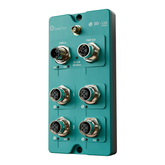
TigoHubi4UserManual Introduction ThisUserManualintroducestheTigoHubi4(P/N:CT261-007-4P)andinstructshowtoperform setup, configuration, mounting, and troubleshooting. TheTigoHubi4isaMultiporthubforIO-LinkWirelessconnectivityofIO-LinkandDIOdevices. Itconnectsup-to4IO-Linkanduptoacombinationof6IO-Link/DIOdevicesandconvertstoIO- Link Wireless. ReadthisUserManualcarefullybeforeusingthedevice. Figure1:TigoHubi4 References: TigoEngine – User Manual TigoMaster2TH–UserManual Page5of41 Copyright©2023CoreTigoLtd. -
Page 6: Structure
TigoHubi4UserManual 1.1. Structure ThesectionsofthisUserManualbuildononeanother. 1.2. TypographicalConventions Enumerationsareshowninlistformwithbulletpoints. Entry1 Entry2 Entry3 Instructionalstepsareshowninlistformwithnumbers. 1. Step1. 2. Step2. 3. Step3. Decimalnumbersareshownwithoutadditionalindicatorsandarenotspelledout(e.g.123). 1.3. Symbols Table1:SymbolsUsed Symbol Meaning Note:Thissymbolindicatesageneralnote. Warning:Thissymbolindicatesasecuritynoticewhichmustbeobserved. Reference:Thissymbolindicatesacross-referencetootherdocumentation. 1.4. DeviatingViews TheproductviewsandillustrationsinthisUserManualmaydeviatefromtheactualproduct.They are intended only as illustrative material. Page6of41 Copyright©2023CoreTigoLtd. -
Page 7: Safety
Limited-EnergyCircuitinaccordancewithUL/CSA61010-1 or LimitedPowerSource(LPS)inaccordancewith(UL/CSA60950-1orEN62368-1,AnnexQ) or Class2supplysourcewhichcomplieswiththeNationalElectricalCode(NEC),NFPA70,Clause 725.121andCanadianElectricalCode(CEC),PartI,C22.1. Warning:WiringofDIOdevicesmustbeaccordingtothespecifiedinstructions.Incorrect wiring may result in damage to the TigoHub i4 and the connected devices. Warning:ProductapplicationsotherthanthosedescribedinthisUserManualarenot permitted. 2.3. IntendedUse TigoHubi4isanIO-LinkWirelessDevicewithanIP65enclosure. TigoHubi4isintendedforindooruseonlyinaserviceareaawayfromthepublicorinapanel. TigoHub i4 converts four IO-Link/DIO ports to a single IO-Link Wireless port. -
Page 8: Personnelqualification
TigoHubi4UserManual 2.4. PersonnelQualification The product may only be Installed, mounted, configured, operated, or demounted by qualified personnel. When working with electricity, technical skills must be demonstrated under all the following circumstances: Safety and health at work Mounting and connecting of electrical equipment ... -
Page 9: Requirements
TigoHubi4UserManual Requirements TigoHubi4isimplementedbasedontheIO-LinkWirelessstandardforW-Devices. TigoHubi4ispart ofanIO-LinkWirelessenvironment.ItcommunicateswithanIO-LinkWireless Master. Therefore, to use it, an IO-Link Wireless Master, IO-Link and DIO devices, and a power cable are required. RefertotheillustrationinFigure2belowforsampleconnectivity: Figure2:TigoHubi4SampleConnectivity IO-LinkClassADevice IO-LinkClassBDevice DIDevices DODevices IO-LinkWirelessMaster PowerSource– 24VDC TigoHubi4 Page9of41 Copyright©2023CoreTigoLtd. -
Page 10: Pre-Installation
4.1. Description IO-Link devices or DI/DO devices can beconnected to aTigoHub i4 using A-codedM12 cables. The TigoHub i4 can be connected to an IO-Link Wireless Master using the TigoEngine engineering tool, the Integrated web server tool, or a PLC. 4.2. -
Page 11: Functionaldiagram
TigoHubi4UserManual 4.3. FunctionalDiagram Figure4:TigoHubi4FunctionalDiagram Powerinput Poweroutput Port1 Port2 Port3 Port4 Antennaconnector Page11of41 Copyright©2023CoreTigoLtd. -
Page 12: Leds
TigoHubi4UserManual 4.4. LEDS Figure5:TigoHubi4 LEDs A. IO-LinkWirelessStatus(Red/Green/Orange) B. PowerSupply1(Red/Green/Orange) C. PowerSupply2(Red/Green/Orange) D. Port 1(Red/Green/Orange) E. Port 2(Red/Green/Orange) F. Port 3(Red/Green/Orange) G. Port 4(Red/Green/Orange) H. DigitalOutput1(Green) DigitalOutput2(Green) Page12of41 Copyright©2023CoreTigoLtd. -
Page 13: Table2:Powerleds
TigoHubi4UserManual 4.4.1. PowerSupplyLEDs ThefollowingtabledescribestheindicationofPowerSupply1andPowerSupply2LEDs Table2:PowerLEDs LEDColor Indication Green PowersupplyvoltageOK 4.4.2. IO-LinkWirelessLEDs Table3:IOLWLEDs LEDColor Indication Green Deviceunpaired BLINKINGGreen(350msecon,350msecoff) Devicepaired FLASHINGGreen(900msecon,100msecoff) Deviceconnected Orange Safemode BLINKINGRed Fault Inactive 4.4.3. PortsLEDs ThefollowingtabledescribetheindicationsofPorts1-4LEDs. Table4:PortsLEDs LEDColor Indication Green PortconfiguredasIOL,operational,invaliddata BLINKINGGreen PortconfiguredasIOL,operational,validdata Orange PortconfiguredasIO,operational,invaliddata BLINKINGOrange PortconfiguredasIO,operational,validdata PortconfiguredasIOL,not operational BLINKINGRed Fault Inactive... -
Page 14: Electricalwiring
TigoHubi4UserManual 4.4.4. DigitalOutputsLEDs ThefollowingtabledescribestheindicationsofDigitalOutputs1-2LEDs. Table5:DigitalOutputsLEDs LEDColor Indication Green Outputsettohigh Outputsetto low 4.5. ElectricalWiring TigoHubi4hassixM12connectors. 4xIO-LinkConnector:5pins,A-Codedfemaleconnector. MaximumCurrentsupplytoIO-Linkdeviceis2Afor24VDCClassAportand4A for 24VDC class B port. PowerInputConnector:5pins,L-Codedmaleconnector. Voltagehigherthan32VDCisforbidden,asitcandamagetheTigoHubi4. Maximum current supply is 8A when using 24VDC. PowerOutputConnector:5pins,L-Codedfemaleconnector. Maximumcurrentsupplyforcascadingpoweris4Apereach1Land2L,when using 24VDC. Page14of41 Copyright©2023CoreTigoLtd. -
Page 15: Electricalconnection
TigoHubi4UserManual 4.6. ElectricalConnection Figure6:ElectricalSchematicDiagram Page15of41 Copyright©2023CoreTigoLtd. -
Page 16: Mounting
TigoHubi4UserManual Mounting TigoHubi4ismountedusing2M4screws,attheholesindicatedinredintheillustrationbelow: Figure7:TigoHubi4Mountings Page16of41 Copyright©2023CoreTigoLtd. -
Page 17: Configurationandsetup
TigoHubi4UserManual ConfigurationandSetup The Process Data (PD) of TigoHub i4 can be configured to define the mapping of the PD of the various connected devices. The configuration, through an internal-IODD (iIODD) table which describes the properties and capabilities of thedevice, is setthroughISDU(Block Parameterization)bytheTigoEngine tothe TigoHub i4, where it is saved in an external flash drive. -
Page 18: Figure8:Pdoutconfigurationexample
TigoHubi4UserManual Table8:PDin/PDoutConfiguration PDin/PDoutConfigurationforPortModeIOLink PDin:canbesettoLengthorOffset PDout:canbesettoLengthorOffset Theusercanalsoconfigurethefollowingparameters: DOinitialvalueincaseofaportmode“CQDO”oriftheIQisenabled,canbeeitherLoworHigh. IOLCycletime(μs–quotedasadecimalnumber) Wiredconnectiontimeout(sec–quotedasadecimalnumber).Thisvaluestateshowmuchtimethe TigoHub i4 should wait for an operational response from the IOL device. Default value = 1 sec. 6.1.1. PDoutConfigurationExample FollowingisanexampleofaPDoutconfiguration(ProcessDataoutfromtheMaster). Table9:PDoutConfigurationExample PDoutConfiguration AggregatedPDoutLength 32(Maximum) Port1 PDoutLength= 14 PDoutOffset=17 Port2 PDoutLength=7 PDoutOffset=0... -
Page 19: Figure9:Pdinconfigurationexample
TigoHubi4UserManual 6.1.2. PDinConfigurationExample FollowingisanexampleofaPDinconfiguration(ProcessDataintotheMaster). Table10:PDinConfigurationExample PDinConfiguration AggregatedPDinLength Port1 PDinLength=2PDinOffset=0 Port2 PDinLength=3PDinOffset=2 Port4 Port 2 CQ Port4 CQ Figure9:PDinConfigurationExample 6.1.3. IO-LinkPortsValidationandBackup ForIOLinkPortsvalidationandbackup,thefollowinguseroptionsareavailable: NONE TYPECOMPATIBLEV10–forrevision1.0ofthewiredstandard TYPECOMPATIBLEV11–forrevision1.1ofthewiredstandard Ifoneoftheabove“TYPECOMPATIBLE”optionsisselected,theusershouldfillthefollowing fields for comparison with the end device: DeviceID VendorID If“NONE”isselected,theabovefieldscanbeleftblank,optionally. Page19of41 Copyright©2023CoreTigoLtd. -
Page 20: Deviceconfiguration
TigoHubi4UserManual Warnings: If a mandatory port is not connected, TigoHub i4 will be set to “Safe Mode”. This means it willnotcommunicateanyPDbetweenthewirelessandthewiredports,evenforconnected ports. ISDU and diagnostic data will still be available. Ifanoptionalportisnotconnected,TigoHubi4willremaininNormalModeandPDforthe rest of the connected ports will be communicated as well as the ISDU and Events. - Page 21 TigoHubi4UserManual 4. ClickonthePRODUCTparameterontheportlisttoviewthedetailsoftheproduct. TheDetailssub-tabopensdisplayingthedetailsofthedevice. 5. ClickonthePortConfigurationsub-tabtoviewthedefinedconfigurationparametersofthis port. Page21of41 Copyright©2023CoreTigoLtd.
- Page 22 TigoHubi4UserManual 6. ClickontheDatasub-tabtowriteandreadon-demand(OD)data. Forexample,toreadthevendorIDofthedevice: UnderISDURead,inserttherelevantdigitsintheIndexandSub-Indexfields. ClicktheReadbuttonontheright-handsideofthescreen. ASuccessnotificationappears. IntheDatafieldselectfromthedropdownlistthedisplayoptionsofDec/Hex/String. TheVendorIDisdisplayedintheDatafield. SimilaractionscanbeperformedinWritemode. 7. ClickontheProcessDatasub-tabtoviewthePDinandPDoutforeachdevice. 8. ClickontheDeviceConfigurationsub-tabtoviewthemainTigoHubi4configurationsetup. Page22of41 Copyright©2023CoreTigoLtd.
- Page 23 TigoHubi4UserManual Prerequisite:WIODDfilesofTigoHubi4shouldbeuploadedbeforehand. Reference:Refertochapter16oftheTigoEngineUserManualforadescriptionof how to upload IODD files. 9. OpentheConfiguratormenu,accessibleintheside-panel,underTigoHubi4Parameters. TheLatestConfigurationConsistencyStatusfielddisplaysinformationregardingany inconsistency errors that may occur during the modification of TigoHub i4 parameters. ModifyingmultipleparametersoftheTigoHubi4ispossible,butsomeinconsistencyerrors may occur after saving the changes. 10. Toeasilyidentifytheseerrors,clicktheReadbutton. AnyinconsistentparameterswillappearintheLatestConfigurationConsistencyStatus field. Page23of41 Copyright©2023CoreTigoLtd.
- Page 24 The Configuratordisplaysallavailableconfigurationscreens. Forinstance,theWiredPort2ParametersscreenshowsinformationregardingPort2of the TigoHub i4. 11. Theusercanconfigureanyoftheportsseparately. For example, to configure Port 1: ClicktheGetAllbuttontoretrievealltheavailabledataforthedevice. ClickonWiredPort1Parametersintheside-panelmenu. ThePort1Configurationscreenopenswiththeretrieveddatapopulated. Forexample: theIOLPDinLengthfielddisplayszerobecausethisdevicehasnoincomingdata. theIOLPDoutLengthfielddisplaysonebecausethisdevicehasoutputdata.Inthis example the relevant device is a smart light connected to the TigoHub i4. Page24of41 Copyright©2023CoreTigoLtd.
- Page 25 TigoHubi4UserManual Theusercanselectvaluesfromthedropdownlistsinanyfieldwithavaluegreaterthanzero. InthedifferentPortParametersdisplays,theusercanselectOffsetvaluesforPDinand PDout. TheIOLPDinLengthdeterminesthenumberofbytestheuserwantstoallocatefromtheIO- Link wired device, and the Wdevice PDin Offset determines the exact byte location from which the data will be aggregated (see the figure above). NotethatthefirstdevicedoesnothavetobeconnectedtoPort1fordataaggregationand connectivity does not have to be sequential. TheusercanselectthetypeofdataforthisPort1,intheCQPortModefieldfromthe options available in the dropdown list – Deactivated/IO Link/DI CQ/DO CQ. (DI=Digital Input, DO=Digital Output).
- Page 26 PDin or PDout will be available, only OD-ISDUs and Diagnostics. Select an option from the available dropdown list – Optional/Mandatory, for this port. Disconnection alerts can be configured in the IODD table. Note:WhenaportisdefinedasMandatoryanditreturnsaCOMLOSTnotificationduring operation, TigoHub i4 will issue an Event and reset itself entering Safe Mode. Ifthedeviceisreconnectedtothisport,TigoHubi4willissueanotherEventandresetitselfentering Regular Mode.
- Page 27 TigoHubi4UserManual 6.2.1. FactorySettings Theusercanreturntheconfiguredvaluestothefactorydefaultvalues.Thiswillreturnthe TigoHub i4 to the default values configured on its flash drive. 1. ClickontheDeviceConfigurationsub-tabtoviewthemainTigoHubi4configurationsetup. Prerequisite:WIODDfilesofTigoHubi4shouldbeuploadedbeforehand. Reference:Refertochapter16oftheTigoEngineUserManualforadescription of how to upload IODD files. 2. OpentheFactorySettingsmenu,accessibleintheside-panel,underTigoHubi4 Parameters. 3. ClicktheRestoreFactorySettingsbutton. AcheckiconappearsalongsidetheRestoreFactorySettingsbutton. Thedeviceresetstothedefaultfactorysettings. Page27of41 Copyright©2023CoreTigoLtd.
- Page 28 TigoHubi4UserManual 4. VerifythisbyaccessingtheDetailssub-tabasshownbelow. 6.2.2. ApplicationSelectors ThisenablestheusertoselectwhichapplicationiscommunicatingwiththeTigoHubi4andby definition all Write and Read actions will be appropriated to the selected device. 1. ClickontheDeviceConfigurationsub-tabtoviewthemainTigoHubi4configurationsetup. Prerequisite:WIODDfilesofTigoHubi4shouldbeuploadedbeforehand. Reference:Refertochapter16oftheTigoEngineUserManualforadescription of how to upload IODD files. Page28of41 Copyright©2023CoreTigoLtd.
- Page 29 TigoHubi4UserManual 2. OpentheApplicationSelectorsmenu,accessibleintheside-panel,underTigoHubi4 Parameters. 3. IntheApplicationSelectorfield,selectfromthedropdownlist,therelevantapplicationto communicate with e.g.TigoHub i4 itself (default) or one of the Wired Ports. 4. IfaWiredPortisselected,afurtherdropdownlistopenstoselecttherelevantwiredport. Page29of41 Copyright©2023CoreTigoLtd.
- Page 30 TigoHubi4UserManual 5. Aftermakingtheselections,clicktheSaveChangesbutton. A Save Changes confirmation box opens. 6. ClicktheSavebutton. ASuccessnotificationappears. 7. VerifythattherelevantapplicationhasbeenselectedbyaccessingtheDetailssub-tab. All of the other sub-tabs are also now updated to reflect the selected application. Page30of41 Copyright©2023CoreTigoLtd.
-
Page 31: Firmwareupdate
TigoHubi4UserManual FirmwareUpdate Firmware(FW)canbeupdatedwirelessly(FOTA)usingtheTigoEngine. Please refer to the TigoEngine User Manual for detailed instructions. ContactCoreTigoSupportifneeded( https://support.coretigo.com/index.php?/home/login Page31of41 Copyright©2023CoreTigoLtd. -
Page 32: Diagnosticsandtroubleshooting
TigoHubi4UserManual DiagnosticsandTroubleshooting TroubleshootingisperformedusingtheLEDsdisplayortheTigoEnginesoftware. Refer to the TigoEngine User Manual for detailed instructions. 8.1. PowerSupplyLEDs ThefollowingtabledescribestheindicationofPowerSupply1andPowerSupply2LEDs Table11:PowerLEDs LEDColor Indication Green PowersupplyvoltageOK 8.2. IOLWLED ThefollowingtabledescribetheindicationsofIOLinkWirelessLEDs. Table12:IOLW LEDs LEDColor Indication Green Deviceunpaired BLINKINGGreen(350msecon,350msecoff) Devicepaired FLASHINGGreen(900msecon,100msecoff) Deviceconnected Orange Safemode BLINKINGRed Fault Inactive 8.3. PortsLEDs ThefollowingtabledescribetheindicationsofPorts1-4LEDs. -
Page 33: Guidelinesandregulations
9.3. ModificationStatements FCCWarning(ModificationStatement) CoreTigo LTD has not approved any changes or modifications to this device by the user. Any changes or modifications can void the user’s authority to operate the equipment. ISEDWarning(ModificationStatement)t) CoreTigo n’approuve aucune modification apportée à l’appareil parl’utilisateur, quelle qu’en soit lanature.Toutchangementoumodificationpeuventannulerledroitd’utilisationdel’appareilpar... - Page 34 TigoHubi4 User Manual This device complies with Part 15 of the FCC Rules.Operation is subject to the following two conditions:(1)this device may not cause interference,and (2)this device must accept any interference, including interference that may cause undesired operation of the device. Le présent appareil est conforme aux CNR d'Industrie Canada applicables aux appareils radio exempts de licence.
-
Page 35: 10. Technicaldata
TigoHubi4UserManual 10. TechnicalData Table14:TechnicalData Electrical Data InputVoltage 18-32VDC.Max.InputCurrent8[A]* TigoHubi4shouldbesuppliedfromalimited,Class2,powersupplyorvia overcurrent protective device (fuse, breacker, etc.) rated 8A max. InputCurrent Max.InputCurrent4[A]pereach1L,2L. OutputVoltageon1L EqualstoInputVoltage OutputVoltageon2L EqualstoInputVoltage TypicalCurrentConsumption 30[mA]** **For24VDCSupplyinput,withoutIOLinkdevicecurrentconsumption. MaxOutputSupplyCurrent MaxOutputSupplyCurrent(cascadingPWRoutport)4[A]pereach 1L, (PWR OUT port) MaxOutputSupplyCurrent 2 [A](1L) (Class A Port) MaxOutputSupplyCurrent 2+2[A] (1L+2L) (Class B Port) MechanicalParameters... - Page 36 TigoHubi4UserManual Interfaces PowerInputconnector:PlugM12,Lcoded Connectors o Pinnumber1:Input1L(PowerSupply1) o Pinnumber2:Input2MGND2 o Pinnumber3:Input1MGND1 o Pinnumber4:Input2L(PowerSupply2) o Pinnumber5:Earthchassis PowerOutputConnector:SocketM12,Lcoded o Pinnumber1:Output1L(PowerSupply1) o Pinnumber2:Output2M(GND2) o Pinnumber3:Output1M(GND1) o Pinnumber4:Output2L(PowerSupply2) o Pinnumber5:Earthchassis Ports[1,2]Connectors:SocketM12,Acoded,ClassB o Pinnumber1:Output1L(PowerSupply1) o Pinnumber2:Output2L(PowerSupply2) o Pinnumber3:Output1M(GND1) o Pinnumber4:IOLCQ(Datasignal) o Pinnumber5:Output2M(GND2) Ports[3,4]Connectors:SocketM12,Acoded,ClassB o Pinnumber1:Output1L(PowerSupply1) o Pinnumber2:DigitalOutput o Pinnumber3:Output1M(GND1)
- Page 37 Safety IEC61010-1 UL61010-1andCSAC22.2No.61010-1 RoHS Complied Reach Complied Qualifications SineVibration: IEC60068-2-6 Shock&Vibrations Randomvibration: IEC60068-2-64 Shock: IEC 60068-2-27 Bumps:IEC60068-2-27 ToreadmoreaboutIO-LinkWirelesssolutionsfollowthislink https://www.coretigo.com/solutions/ OperatingConditions OperatingTemperature -20° Cto65° C RelativeHumidityRating RH5%to93%,non-condensing Altitude Upto 2000m Pollution Degree3 IPRating IP65 EN61000-6-2 Emission...
-
Page 38: Figure10:Blockdiagram-Power
TigoHubi4UserManual BlockDiagrams Figure10:BlockDiagram- Power Figure11:BlockDiagram-Ports1and2 Page38of41 Copyright©2023CoreTigoLtd. -
Page 39: Figure12:Blockdiagram-Ports3And4
TigoHubi4UserManual Figure12:BlockDiagram-Ports3and4 Page39of41 Copyright©2023CoreTigoLtd. -
Page 40: 11. Customersupport
TigoHubi4UserManual Dimensions 11. CustomerSupport Foranyissue,question,ortoreportabug,contact support@coretigo.com Or visitourCustomerSuccessPortalat: <https://support.coretigo.com/index.php?/home/login> Page40of41 Copyright©2023CoreTigoLtd. -
Page 41: Appendix-Partnumber
TigoHubi4UserManual Appendix–PartNumber Partnumber:CT221-0057-03 Generation:2 ProductIdentifier:2 ProductType:1 Protocol: 0057 Characters IdentifierofFeatures Version:03 CT(GXY-ZZZZiii-vv) ZZZZ Feature’sCharacter Generation Product Product Protocol Version Identifier Type Identifier Page41of41 Copyright©2023CoreTigoLtd.
Need help?
Do you have a question about the TigoHub i4 and is the answer not in the manual?
Questions and answers