Advertisement
PAN05-1B/-2B/-3B
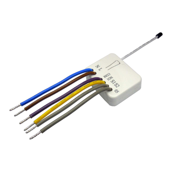
In Wall Single relay (1 way) switch
module
Fig 1. Assembling
This in-wall switch module is a transceiver which is a security enabled device which
based on Z-Wave Plus technology, and it is fully compatible with any Z-Wave
enabled network. Mini size design let the module can easily hide itself into the wall
P
box and that will be good for the house decoration. Since PAN05 supports Security
Command Class, it can learn with Secured controller. Its functionality and supported
command classes is identical when included as a secure and non-secure device.
There are many kind of application by using the module to switch Load On and Off,
one main application is the light control. If connect the COM terminal directly to AC
Line terminal, the new smart relay calibration technology can reduce the inrush
current caused by the load and let the module work perfectly with many kind of light
like incandescent, fluorescent and LED light. This module can also connect to
alternative power supply like DC 12V to switch on/off 12V MR-16 light as follow
picture.
Adding to Z-Wave
In the front casing, there is an on/off button with LED indicator below which is used to
toggle switch on and off or carries out inclusion, exclusion, reset or association.
When first power applied, its LED flashes on and off alternately and repeatedly at 0.5
second intervals. It implies that it has not been assigned a node ID and start auto
inclusion.
Auto Inclusion
1
TM
Network
TM
Advertisement
Table of Contents

Related Manuals for Z-Wave PAN05-1B


Summary of Contents for Z-Wave PAN05-1B
- Page 1 This in-wall switch module is a transceiver which is a security enabled device which based on Z-Wave Plus technology, and it is fully compatible with any Z-Wave enabled network. Mini size design let the module can easily hide itself into the wall box and that will be good for the house decoration.
-
Page 2: Led Indication
Including a node ID allocated by Z-Wave Controller means inclusion. Excluding a node Setup function, and to include/exclude/associate devices ID allocated by Z-Wave Controller means exclusion. Failed or success in including/excluding the node ID can be viewed from the Z-Wave Controller. Function... -
Page 3: Choosing A Suitable Location
3. There are 3 mode PAN05 can be configured to match different kind of wall switch, The Switch can be set to send reports to associated Z-Wave devices. It supports only please refer to 3-1 Edge / Pulse / Edge-Toggle mode which described in next one association group and the group has one node support. - Page 4 = 0x08, Alarm Level = 0xFF] if the PAN05 relay change the state because of receiving Z-Wave RF 2. Z-Wave’s Configuration command, it may need two times of change (switch on to off or switch off to on) to let relay back to the correspond state.
-
Page 5: Troubleshooting
Whenever the AC power reconnected to PAN05, it will set the switch to Off、On or change. Last switch state, default value is Last switch state. However, the operation of learn function does not change, because learning will 3-3 Manual On/Off Mode not be protected. -
Page 6: Fcc Interference Statement
continuously, but cannot max. load cannot exceed FCC Interference Statement FCC Interference Statement FCC Interference Statement FCC Interference Statement control 85 ° C (230Vac/120Vac) (Resistive load) This equipment has been tested and found to comply with the limits for Specification a Class B digital device, pursuant to Part 15 of the FCC Rules. - Page 7 operate this equipment. This transmitter must not be co-located or operating in conjunction with any other antenna or transmitter.
Need help?
Do you have a question about the PAN05-1B and is the answer not in the manual?
Questions and answers