
Related Manuals for LOGSMITH BM11119

Summary of Contents for LOGSMITH BM11119
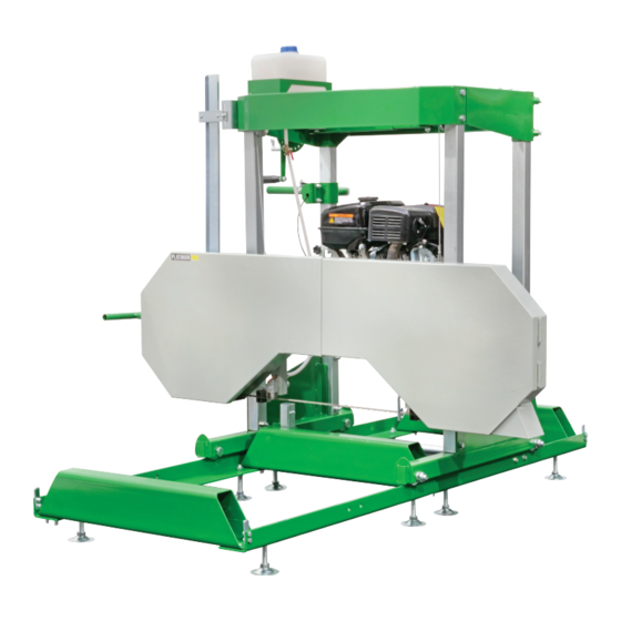
- Page 1 15HP 26" Petrol Sawmill Bandsaw Mill with E-start BM11119 Read this material before using this product. Failure to do so can result in serious injury. SAVE THIS MANUAL...
- Page 2 Table of Contents Safety ............3 Maintenance ..........12 ..........6 Parts List and Diagrams ......14 Assembly ............ 6 Operation........... 10 WARNING SYMBOLS AND DEFINITIONS This is the safety alert symbol. It is used to alert you to potential personal injury hazards. Obey all safety messages that follow this symbol to avoid possible injury or death.
- Page 3 IMPORTANT SAFETY INFORMATION WARNING! Read all instructions. The warnings and precautions discussed in this manual cannot cover all possible conditions and situations that may occur. It must be understood by the operator that common sense and caution are factors which cannot be built into this product, but must be supplied by the operator. SAVE THESE INSTRUCTIONS Set Up Precautions agencies for laws or regulations relating...
- Page 4 8. Do not operate in explosive atmospheres, 18. WARNING: Some dust created by power sanding, sawing, grinding, drilling, and other construction liquids, gases, or dust. Gasoline-powered activities, contains chemicals known [to the State engines may ignite the dust or fumes. of California] to cause cancer, birth defects or other reproductive harm.
- Page 5 Service Precautions 1. Before service, maintenance, or cleaning: person using only identical replacement parts. a. Turn the engine switch to its “OFF” position. This will ensure that the safety of the equipment b. Allow the engine to completely cool. is maintained. Do not attempt any service or maintenance procedures not explained in this c.
- Page 6 Log Diameter 87+ octane unleaded Type gasoline Board Width Fuel Capacity 1 Gallon Cutting Thickness Coolant Tank Capacity 4.2 Quarts Cutting Length Blade Speed 3,279 FPM Note: engine manual supplied with this equipment. Assembly Read the ENTIRE IMPORTANT SAFETY INFORMATION section at the beginning of this manual including all text under subheadings therein before set up or use of this product.
- Page 7 can move smoothly on the round post. Then secure 6. Use the Bolts (22) and Nuts (25) to fasten the End it in place with the Right Lock Handle (59). Stops (79) to the Track Sections, as shown below. Round Post (20) Blade 7.
- Page 8 10. Place the Top Frame (23) on the Posts (20, 48). 15. Thread the Cable Anchor Bolts (46) into the Blade Guard (50) as shown below. Figure G: Top Frame 11. Secure the two Bolts (22) attaching the Top Frame (23) to the Figure K: Cable Anchor Bolt Locations Round Post (20) as shown below.
- Page 9 18. Slide Fixed Block until it gently touches the Blade. Refer to Figure O for the following instructions: Then tighten the Bolt, fastening it in place. BEFORE any adjustment, loosen Bolts See below. Repeat for the remaining Fixed E and F and Nuts C and D. between Fixed Blocks and Blade.
- Page 10 Operating Instructions Read the ENTIRE IMPORTANT all text under subheadings therein SAFETY INFORMATION section at the before set up or use of this product. beginning of this manual including Engine Operation Inspect engine and equipment looking instructions in the separate engine for damaged, loose, and missing manual provided with the engine.
- Page 11 11. Align the Blade with the top of the lumber, loosen the WARNING! The operator and any assistants Scale Knob and adjust the Scale Pointer to point at must stay clear of the front and back of the blade whenever the engine is running. Scale 15.
- Page 12 Servicing TO PREVENT SERIOUS INJURY FROM ACCIDENTAL STARTING: Turn the Power Switch of the equipment to its “OFF” position, wait for the engine to cool, and disconnect the spark plug wire(s) before performing any inspection, maintenance, or cleaning procedures. TO PREVENT SERIOUS INJURY FROM EQUIPMENT FAILURE: Do not use damaged equipment.
- Page 13 Equipment Troubleshooting Problem Possible Causes Probable Solutions Excessive blade 1. Increase blade tension. breakage. 2. Incorrect speed or feed rate. 2. Adjust speed or feed rate for the lumber being cut. 3. Lumber loose. 3. Make sure lumber is securely positioned against supports.
- Page 14 Parts List and Diagrams Parts List Part Description Part Description Wheel Hex Nut M12 Hex Nut M20 Hex Bolt M12×100 Left Wheel Frame Left Lock Handle Clamp 1 Hex Bolt M8×45 Hex Nut M12 Support Tube Hex Bolt M20×100 Beam Right Wheel Frame Hex Bolt M12×80 Hex Bolt M12×80...
- Page 15 Assembly Diagram Page 15...
- Page 16 Assembly Diagram (continued) Page 16...
- Page 17 Assembly Diagram (continued) Page 17...
Need help?
Do you have a question about the BM11119 and is the answer not in the manual?
Questions and answers