Table of Contents
Advertisement
Quick Links
Advertisement
Table of Contents

Subscribe to Our Youtube Channel
Related Manuals for Kicker KEYLOC


Summary of Contents for Kicker KEYLOC
- Page 1 Owner’s Manual KEYLOC DSP-Powered Line Output Converter...
-
Page 2: Table Of Contents
Contents Overview ......3 Specifi cations ......4 Installation ...... 5 Mounting ....... 5 Wiring ........6 Operation ....... 9 Signal Identifi cation ....10 Signal Restoration ....11 Line-Output Conversion ..16 Troubleshooting .... 17 English... -
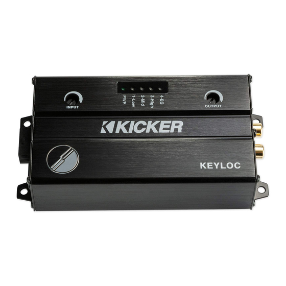
Page 3: Overview
VENTILATION. SUBWOOFERS SHOULD BE MOUNTED WITH AT LEAST 1 INCH (2.5CM) CLEARANCE BETWEEN THE FRONT OF THE SPEAKER AND ANY SURFACE. KICKER PRODUCTS ARE CAPABLE OF PRODUCING SOUND LEVELS THAT CAN PERMANENTLY DAMAGE YOUR HEARING! TURNING UP A SYSTEM TO A LEVEL THAT HAS AUDIBLE DISTORTION IS MORE DAMAGING TO YOUR EARS THAN LISTENING TO AN UNDISTORTED SYSTEM AT THE SAME VOLUME LEVEL. -
Page 4: Specifi Cations
Specifi cations Model: KEYLOC Rated Output per channel 1KHz @ 14.4V, ≤ 1% THD+N Length [in, cm] 5-1/2, 14 Height [in, cm] 1-3/8, 3.5 Width [in, cm] 2-3/4, 7.1 Frequency Response 20Hz–20kHz Signal-to-Noise Ratio >90dB, A-weighted, re: rated power Input Sensitivity Lo: 250mV–10V - Fixed 60Ω... -
Page 5: Installation
KEYLOC. Make sure there are no items behind the area where the screws will be driven. If possible, mount the KEYLOC behind the dash or in the climate- controlled passenger compartment. Drill four holes using a 7/64” (3mm) bit and use the supplied #8... -
Page 6: Wiring
If your head unit has a remote output you can connect this to the remote input of the KEYLOC. If your head unit does not have a remote output, the KEYLOC can use the DC offset that is present on the speaker outputs of most factory head units. - Page 7 125mV-10V. The HI range can accept 1V – 40 V. The KEYLOC can output up to 10V of preamp RCA level output, adjustable with the Output Gain knob. In the LO range, there is a 60Ω load for use with newer smart radios that shut off their outputs if they do not detect a speaker.
- Page 8 USB for internal use only RCA Outputs (to amplifi er)
-
Page 9: Operation
Operation The KEYLOC is a 2-channel DSP based active line output converter with the following features. Automatic Turn-on: DC offset remote input turn-on, and remote output turn-on (100mA) to turn on other products. Frequency Response Correction: Smooths frequency response of two channels from your source unit via EQ correction. -
Page 10: Signal Identifi Cation
The KEYLOC will help you identify the correct OEM wires to which you should connect using the following steps: 1. Turn the Input Gain on the KEYLOC all the way down. 2. Turn the audio source up to at least 1/2 volume. -
Page 11: Signal Restoration
During the key process if you accidentally push the KEY button before playing the NOISE FLOOR track, the KEYLOC will have an error and all LEDs will fl ash. You must then press the KEY button to exit the KEY process. - Page 12 Automatic Setup: 1. Verify the input gain of the KEYLOC is turned all the way down. Set the source unit between ½ and ¾ volume, or just before it starts to clip. Make sure all tone controls (Bass, Mid, Treble) are set to fl at. It is very important that the source unit’s audio outputs are...
- Page 13 The FullTest track is 22 minutes long, however most corrections will only take between three to eight minutes. 9. The LEDs will begin to fl ash once the KEYLOC has collected enough data and is processing the test results. 10. The LEDs will sweep back and forth when the algorithm has completed, and audio will begin passing.
- Page 14 Navigating the Menu: After the Auto setup process has completed, you’ll be able to navigate the KEYLOC menu using the KEY button and LEDs. To enter the menu, press and hold the KEY button for 4 seconds. You will see the LEDS sweep 1-4 - release the KEY button.
- Page 15 LED2 - Gain Match Status LED 2 indicates Left/Right Channel gain matching status. Solid: On Blinking: Off LED3 - Reset KEYLOC Hold the KEY button for 10 seconds LED4 - Exit the Menu Hold the KEY button for 1 second to exit the menu...
-
Page 16: Line-Output Conversion
Line-Output Conversion After Auto Setup is complete, use the Output Gain to match the output voltage of the KEYLOC to the input sensitivity voltage of your amplifi er. If you’re not using gain match capable electronics or a voltmeter/ multimeter, listening for audible distortion is always the next best way to set your gain. -
Page 17: Troubleshooting
3. In most aftermarket systems in which you will not be using a fully active DSP after the KEYLOC in the signal chain, you will likely want to turn off the All pass/Time delay defeat for the best stereo imaging. - Page 18 KEYLOC frozen or stuck in operating procedure? Cycle the power Reset the remote Reset the KEYLOC Alternator noise-whining sound with engine’s RPM? Check for damaged RCA (or speaker input) cable Check the routing of RCA (or speaker input) cable ...
Need help?
Do you have a question about the KEYLOC and is the answer not in the manual?
Questions and answers