
Summary of Contents for BeiJer BFI-H3-22-0043-1F12-MN
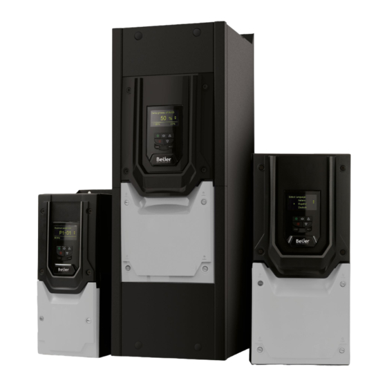
- Page 1 HVAC Inverter H3 AC Variable Speed Drives for Fan & Pump 0.75 - 250kW 200 - 480V IP20 - IP55 / NEMA 12 – IP66 / NEMA 4...
-
Page 2: Table Of Contents
5.8. Keypad Shortcuts ......2 | Beijer BFI-H3 User Guide | Version 3.08... - Page 3 P0-28. User Guide Revision 3.08 Beijer Electronics adopts a policy of continuous improvement and whilst every effort has been made to provide accurate and up to date information, the information contained in this User Guide should be used for guidance purposes only and does not form the part of any contract.
-
Page 4: Introduction
Ensure that all terminals are tightened to the appropriate torque setting. Do not attempt to carry out any repair of the BFI drive. In the case of suspected fault or malfunction, contact Beijer Electronics for further assistance. 4 | Beijer BFI-H3 User Guide | Version 3.08... -
Page 5: General Information And Ratings
Low Harmonic BFI-H3-24-0022-3F12-MN 0.75 BFI-H3-24-0041-3F12-MN 4. 1 BFI-H3-24-0058-3F12-MN BFI-H3-24-0095-3F12-MN BFI-H3-34-0140-3F12-MN BFI-H3-34-0180-3F12-MN BFI-H3-34-0240-3F12-MN BFI-H3-44-0300-3F12-MN BFI-H3-44-0390-3F12-MN 18.5 BFI-H3-44-0460-3F12-MN BFI-H3-54-0610-3F12-MN BFI-H3-54-0720-3F12-MN BFI-H3-54-0900-3F12-MN BFI-H3-64-1 100-3F12-MN 1 10 BFI-H3-64-1500-3F12-MN BFI-H3-64-1800-3F12-MN BFI-H3-64-2020-3F12-MN 1 10 BFI-H3-84-3700-3F12-TN BFI-H3-84-4500-3F12-TN www.beijerelectronics.com Version 3.08 | Beijer BFI-H3 User Guide | 5... - Page 6 With Disconnect Frame Amps Low Harmonic BFI-H3-24-0022-3F1A-MN BFI-H3-24-0022-3F1E-MN 0.75 BFI-H3-24-0041-3F1A-MN BFI-H3-24-0041-3F1E-MN 4. 1 BFI-H3-24-0058-3F1A-MN BFI-H3-24-0058-3F1E-MN BFI-H3-24-0095-3F1A-MN BFI-H3-24-0095-3F1E-MN BFI-H3-34-0140-3F1A-MN BFI-H3-34-0140-3F1E-MN BFI-H3-34-0180-3F1A-MN BFI-H3-34-0180-3F1E-MN BFI-H3-34-0240-3F1A-MN BFI-H3-34-0240-3F1E-MN BFI-H3-34-0300-3F1A-MN BFI-H3-34-0300-3F1E-MN BFI-H3-44-0390-3F1A-MN BFI-H3-44-0390-3F1E-MN 18.5 BFI-H3-44-0460-3F1A-MN BFI-H3-44-0460-3F1E-MN 6 | Beijer BFI-H3 User Guide | Version 3.08 www.beijerelectronics.com...
- Page 7 2.1.4. Low Harmonic Variants The majority of the Beijer BFI-H3 product range is based on a low harmonic solution using film capacitor technology to achieve compliance with EN 61000-3-12 without the need for any additional equipment. This standard specifies limits for harmonic currents for equipment connected to public low-voltage systems with input current >...
-
Page 8: Identifying The Drive By Model Number
1: No internal Brake Chopper No. of input phases EMC Filter 1 = Single Phase Input 0 : No Internal Filter 3 = 3 Phase Input F : Internal Filter 8 | Beijer BFI-H3 User Guide | Version 3.08 www.beijerelectronics.com... -
Page 9: Mechanical Installation
NOTE This procedure is only required for non low harmonic version - see section 2. 1 .4. Low Harmonic Variants on page 7. www.beijerelectronics.com Version 3.08 | Beijer BFI-H3 User Guide | 9... -
Page 10: Mechanical Dimensions And Weight
*The IP20 Frame Size 4 Chassis can obstruct the rotation (tightening) of a bolt or screw with a hex head, a fixing with a round head will be most suitable for the mounting of this unit. 10 | Beijer BFI-H3 User Guide | Version 3.08 www.beijerelectronics.com... - Page 11 Required Torque 5/16 Control Terminals 0.5 Nm 4.5 lb-in 2 Nm 18 lb-in 5/16 4 Nm 35.5 lb-in Power Terminals 15 Nm 1 1 lb-ft 15 Nm 1 1 lb-ft www.beijerelectronics.com Version 3.08 | Beijer BFI-H3 User Guide | 11...
- Page 12 Metric Frame Size Required Torque All Sizes Control Terminals 2, 3 & 4 0.5 Nm 4.5 lb-in 2 & 3 0.8 Nm 7 lb-in Power Terminals 2 Nm 19 lb-in 12 | Beijer BFI-H3 User Guide | Version 3.08 www.beijerelectronics.com...
-
Page 13: Guidelines For Enclosure Mounting (Ip20 Units)
High moisture, salt or chemical content environments should use a suitably sealed (non-vented) enclosure. The enclosure design and layout should ensure that the adequate ventilation paths and clearances are left to allow air to circulate through the drive heatsink. Beijer Electronics recommend the following minimum sizes for drives mounted in non-ventilated metallic enclosures: Above &... -
Page 14: Mounting The Drive - Ip20 Units
P = Total power dissipated in panel (include all losses from all power devices) T = Maximum temperature allowed in the panel (ambient temperature for the drive) T = Maximum ambient temperature around the panel 14 | Beijer BFI-H3 User Guide | Version 3.08 www.beijerelectronics.com... -
Page 15: Guidelines For Mounting (Ip55 Units)
Typical drive heat losses are approximately 2% of the operating load power. The above dimensions are for guidance only, the operating ambient temperature of the drive MUST be maintained within the specified limits or allowed derating at all times. www.beijerelectronics.com Version 3.08 | Beijer BFI-H3 User Guide | 15... -
Page 16: Guidelines For Mounting (Ip66 Units)
F or conduit installations the conduit entry holes require standard opening to the required sizes specified per the NEC. N ot intended for installation using rigid conduit system. 16 | Beijer BFI-H3 User Guide | Version 3.08 www.beijerelectronics.com... -
Page 17: Installing The Ip66 Sun Shade
0. 1 9 1.5 3.3 3 & 4 340.7 13.41 169.7 6.68 324.7 12.78 307.3 12. 1 180.0 7.09 99.6 3.92 48.9 1.93 355.0 14.0 4.8 0. 1 9 2.5 5.5 www.beijerelectronics.com Version 3.08 | Beijer BFI-H3 User Guide | 17... -
Page 18: Removing The Terminal Cover
Ensure any panel ventilation fans and air filters are clean and provide the correct required air flow. C hecks should also be made on all electrical connections, ensuring screw terminals are correctly torqued; and that power cables have no signs of heat damage. 18 | Beijer BFI-H3 User Guide | Version 3.08 www.beijerelectronics.com... -
Page 19: Ip66 (Nema 4X) Lock Off
Mains switch-disconnector Lock Off On the switched models the mains switch-disconnector can be locked in the ‘Off’ position using a 20mm standard shackle padlock (not supplied). IP66 / NEMA 4X Unit Lock Off www.beijerelectronics.com Version 3.08 | Beijer BFI-H3 User Guide | 19... -
Page 20: Electrical Installation
NOTE Enclosed drives are not suitable for rigid conduit system connection. This manual is intended as a guide for proper installation. Beijer Electronics cannot assume responsibility for the compliance or the non-compliance to any code, national, local or otherwise, for the proper installation of this drive or associated equipment. -
Page 21: Protective Earth (Pe) Connection
(drive end) should also be connected to the motor frame (motor end). Use a shield terminating or EMI clamp to connect the shield to the safety ground terminal, refer to section 4.3. EMC Compliant Installation on page 22. www.beijerelectronics.com Version 3.08 | Beijer BFI-H3 User Guide | 21... -
Page 22: Emc Compliant Installation
IP20, IP66 4, 5 IP20, IP55 6A, 6B IP20 6, 7 IP55 25 (100) IP20 NOTE D ata in brackets shows permissible cable length with additional external EMC filter. 22 | Beijer BFI-H3 User Guide | Version 3.08 www.beijerelectronics.com... - Page 23 1 2 3 4 5 6 7 8 9 10 11 L2/N Shield Drain Shield Drain Wire Wire IP20 Frame size 2,3 & 4 IP20 Frame size 5, 6A & 6B – www.beijerelectronics.com Version 3.08 | Beijer BFI-H3 User Guide | 23...
-
Page 24: Incoming Power Connection
4.5. Input Chokes T he majority of the Beijer BFI-H3 product range is based on a low harmonic solution using film capacitor technology to achieve compliance with EN 61000-3-12 without the need for any additional equipment. This standard specifies limits for harmonic currents for equipment connected to public low-voltage systems with input current >... -
Page 25: Drive And Motor Connection
Incoming Supply Voltage Motor Nameplate Voltages Connection 230 / 400 400 / 460 400 / 690 Delta 575 / 1000 230 / 400 Star 330 / 575 www.beijerelectronics.com Version 3.08 | Beijer BFI-H3 User Guide | 25... -
Page 26: Motor Thermal Overload Protection
4.8.1. Internal Thermal Overload Protection Beijer BFI-H3 has internal motor overload protection (current limit) set at 1 10% of the motor rated current (P1-08). This level may be adjusted in P4-07. The drive has an in-built motor thermal overload function; this is in the form of an “I.t-trP” trip after delivering >100% of the value set in P1-08 (motor rated current) for a sustained period of time. - Page 27 Analog Outputs: 0 – 10 Volt / 4-20mA (20mA max) SAFE TORQUE OFF input: Logic High = 18-30 Vdc (Also refer to section 4. 1 1. Safe Torque Off on page 29) www.beijerelectronics.com Version 3.08 | Beijer BFI-H3 User Guide | 27...
-
Page 28: Control Terminal Connections
Analog Output 1 P2-1 1 P2-12 Analog Output 2 P2-13 P2-14 These parameters are described more fully in section 8. 1 . Digital Input Configuration Parameter P1-13 on page 41. 28 | Beijer BFI-H3 User Guide | Version 3.08 www.beijerelectronics.com... -
Page 29: Safe Torque Off
When using permanent magnet motors and in the unlikely event of a multiple output power device failing then the motor could effectively rotate the motor shaft by 180/p degrees (Where p denotes number of motor pole pairs). www.beijerelectronics.com Version 3.08 | Beijer BFI-H3 User Guide | 29... - Page 30 The drive should be wired as illustrated below; the 24Vdc signal source applied to the “STO” input can be either from the 24Vdc on the drive or from an External 24Vdc power supply. 30 | Beijer BFI-H3 User Guide | Version 3.08 www.beijerelectronics.com...
- Page 31 NOTE The Maximum cable length from Voltage source to the drive terminals should not exceed 25 metres. 4.11.8. External Power Supply Specification Voltage Rating (Nominal) 24Vdc STO Logic High 18-30Vdc (Safe torque off in standby) Current Consumption (Maximum) 100mA www.beijerelectronics.com Version 3.08 | Beijer BFI-H3 User Guide | 31...
- Page 32 (Minimum once per year), furthermore the function should be integrity tested following any safety system modifications or maintenance work. If drive fault messages are observed refer to section 12. 1 . Fault Messages for further guidance. 32 | Beijer BFI-H3 User Guide | Version 3.08 www.beijerelectronics.com...
-
Page 33: Keypad And Display Operation
Hand Button in parameter edit mode. Used to place drive in Hand (keypad) mode. Auto Button Used to place drive in Auto (Remote) mode. www.beijerelectronics.com Version 3.08 | Beijer BFI-H3 User Guide | 33... -
Page 34: Selecting The Language On The Tft & Oled Display
9.3. Parameter external 24 Volt source, with exceeds the motor rated Group 4 – High Performance no mains power applied. current entered in Parameter Motor Control on page 48. P1-08. 34 | Beijer BFI-H3 User Guide | Version 3.08 www.beijerelectronics.com... -
Page 35: Changing Parameters
Display will show the and minimum possible present parameter settings on the lower value on the lower line of the display. line of the display. www.beijerelectronics.com Version 3.08 | Beijer BFI-H3 User Guide | 35... -
Page 36: Parameter Factory Reset / User Reset
5.5. Parameter Factory Reset / User Reset Beijer BFI-H3 provides a feature to allow the user to define their own default parameter set. After commissioning all required parameters, the user can save these as the default parameters by setting P6-29 = 1. If required, the User Default Parameters may be cleared by setting P6-29 = 2. -
Page 37: Keypad Shortcuts
Stop and parameter selection keys simultaneously. press will move and down keys. Navigate will return the menu. another digit to the cursor to the right most left. digit. www.beijerelectronics.com Version 3.08 | Beijer BFI-H3 User Guide | 37... -
Page 38: Commissioning
6.1.2. Minimum and Maximum Frequencies / Speeds Beijer BFI-H3 units are factory set to operate the motor from zero up to base speed (50 or 60Hz output). In general, this operating range is suitable for a wide range of requirements, however in some cases it may be desired to adjust these limits, e.g. where the maximum speed of a fan or pump may provide excessive flow, or where operation below a certain speed is never required. -
Page 39: Parameters
7. Parameters 7.1. Parameter Set Overview The Beijer BFI-H3 Extended Parameter set consists of 7 groups as follows: Group 1 – Basic Parameter Set Group 2 – Extended Parameter Set Group 3 – User PID Control Parameter Set Group 4 –... - Page 40 P1-14 <> P2-40 and P1-14 <> P6-30: Allows access to Parameter Group 1 only. P1-14 = P2-40 (101 default): Allows access to Parameter Groups 0 - 5 and group 8. P1-14 = P6-30 (201 default): Allows access to Parameter Groups 0 - 9. 40 | Beijer BFI-H3 User Guide | Version 3.08 www.beijerelectronics.com...
-
Page 41: Control Terminal Functions
10 to allow selection between two independent digital references using digital input 2. Digital preset reference 1 and 2 are set in P3-06 and P3-15 respectively. “Motor thermistor trip” connection is via analog input 2 and is configured by parameter P2-33 (Pt-th). NOTE www.beijerelectronics.com Version 3.08 | Beijer BFI-H3 User Guide | 41... -
Page 42: Extended Parameters
0 to 200% of P1-08. Motor torque 0 to 200% of motor rated torque. Motor power 0 to 150% of drive rated power. PID Output Output from the internal PID Controller, 0 – 100%. 42 | Beijer BFI-H3 User Guide | Version 3.08 www.beijerelectronics.com... - Page 43 - = 0 to10V - = 10 to 0V - = 0 to 20mA - = 20 to 0mA - = 4 to 20mA - = 20 to 4mA www.beijerelectronics.com Version 3.08 | Beijer BFI-H3 User Guide | 43...
- Page 44 Sets the upper limited value for P2-13 and P2-18, please refer to P2-13 or P2-18. P2-20 Relay 2 / AO2 Lower Limit P2-19 Sets the lower limited value for P2-13 and P2-18, please refer to P2-13 or P2-18. 44 | Beijer BFI-H3 User Guide | Version 3.08 www.beijerelectronics.com...
- Page 45 - = 20 to 4mA Signal, the BFI drive will trip and show the fault code -F if the signal level falls below 3mA. - = 20 to 4mA Signal, the BFI drive will ramp to preset speed 4 (P2-04) if the signal level falls below 3mA. www.beijerelectronics.com Version 3.08 | Beijer BFI-H3 User Guide | 45...
- Page 46 BFI drive. 3 : Main Loss Disabled (DC-bus supply feed mode). Drive is powered through DC bus link directly. No supply feed connected to the input terminals. 46 | Beijer BFI-H3 User Guide | Version 3.08 www.beijerelectronics.com...
-
Page 47: Parameter Group 3 - Pid Control
4 : Analog input 1 – Analog input 2. Differential of Analog 1 – Analog 2 = 0 – 100.0%. 5 : Largest (analog input 1, analog input 2). The greater of Analog input 1 or Analog Input 2 is always used. www.beijerelectronics.com Version 3.08 | Beijer BFI-H3 User Guide | 47... -
Page 48: Parameter Group 4 - High Performance Motor Control
When set to 1, the drive immediately carries out a non-rotating auto-tune to measure the motor parameters for optimum control and efficiency. Following completion of the auto-tune, the parameter automatically returns to 0. 48 | Beijer BFI-H3 User Guide | Version 3.08 www.beijerelectronics.com... -
Page 49: Parameter Group 5 - Communication Parameters
Controls the behaviour of the drive following a loss of communications as determined by the above parameter setting (P5-06). 0 : Trip & Coast To Stop 1 : Ramp to Stop Then Trip 2 : Ramp to Stop Only (No Trip) 3 : Run at Preset Speed 4 www.beijerelectronics.com Version 3.08 | Beijer BFI-H3 User Guide | 49... - Page 50 If this parameter is set to a value greater than 0, this address will become the Drive Modbus address. If this value is set to 0, P5-01 determines the Drive Modbus address. 50 | Beijer BFI-H3 User Guide | Version 3.08 www.beijerelectronics.com...
-
Page 51: Advanced Parameters
-500.0 – 500.0% 0.0% P6-28 P0-80 Display Index 0 - 200 P6-29 User Default Parameters No Function Save user parameters Clear user parameters P6-30 Level 3 (Advanced) Access Code 0 – 9999 www.beijerelectronics.com Version 3.08 | Beijer BFI-H3 User Guide | 51... -
Page 52: Parameter Group 8 - Application Function Specific Parameters
Pump Clean Time Seconds Sets the time period for the operation of the pump cleaning cycle. When bi-directional pump cleaning is selected, the time interval is used twice, once in each direction. 52 | Beijer BFI-H3 User Guide | Version 3.08 www.beijerelectronics.com... - Page 53 Care must be taken when setting P8-13 to ensure that drive and DOL contactors are not switched in circuit simultaneously. Both Mechanical and Electrical interlocking of drive and DOL contactors to regional standards are recommended in configuring the Bypass function. www.beijerelectronics.com Version 3.08 | Beijer BFI-H3 User Guide | 53...
-
Page 54: Fire Mode
If Fire Mode speed is set (<>0) in P8-10, when fire mode is activated, the drive will enter Fire Mode and run at the speed set in P8-10 and will ignore all other terminals with the exception of the STO. 54 | Beijer BFI-H3 User Guide | Version 3.08 www.beijerelectronics.com... -
Page 55: Parameter Group 9 - User Inputs And Output Programming
Parameters are only adjustable if P1-13 = 0. This allows complete flexibility over the drive control P9-43 Bypass Mode Trigger Source functions, and interaction with the internal Function Block programming environment. P9-44 PID Second Digital Ref Select www.beijerelectronics.com Version 3.08 | Beijer BFI-H3 User Guide | 55... -
Page 56: Parameter Group 0 - Monitoring Parameters (Read Only)
Displays the amount of time in hours and minutes that the BFI drive has operated for during its lifetime with a heatsink temperature in excess of 85°C. This parameter is used by the BFI drive for various internal protection and monitoring functions. 56 | Beijer BFI-H3 User Guide | Version 3.08 www.beijerelectronics.com... - Page 57 Diagnostic log for DC bus voltage ripple. Values logged every 20mS with 8 samples total. Logging suspended on drive trip. P0-38 Heatsink Temperature Log (30s) °C Diagnostic log for heatsink temperature. Values logged every 30S with 8 samples total. Logging suspended on drive trip. www.beijerelectronics.com Version 3.08 | Beijer BFI-H3 User Guide | 57...
- Page 58 Modbus RTU / BACnet MSTP Fault Counter This parameter is incremented every time an error occurs on the Modbus RTU communication link. This information can be used for diagnostic purposes. 58 | Beijer BFI-H3 User Guide | Version 3.08 www.beijerelectronics.com...
-
Page 59: Serial Communications
10.1. RS-485 Communications Beijer BFI-H3 has an RJ45 connector located within the wiring enclosure of the drive. This connector allows the user to set up a drive network via a wired connection. The connector contains two independent RS485 connections, one for Beijer Electronics’s Serial Bus Protocol and one for Modbus RTU / BACnet MSTP. -
Page 60: Modbus Rtu Communications
10.2.1. Modbus Telegram Structure The Beijer BFI-H3 supports Master / Slave Modbus RTU communications, using the 03 Read Multiple Holding Registers and 06 Write Single Holding Register commands and 16 Write Multiple Holding Registers (Supported for registers 1 – 4 only). Many Master devices treat the first Register address as Register 0;... - Page 61 Read Value of P1-01 = 500, therefore this is 50.0Hz. For further details on communicating with BFI drives using Modbus RTU, please refer to Beijer Electronics. www.beijerelectronics.com Version 3.08 | Beijer BFI-H3 User Guide | 61...
-
Page 62: Bacnet Mstp
10.3.1. Overview Beijer BFI-H3 provides an interface for direct connection to a BACnet MSTP network. Connection is made via the RJ45 connection port, see section 10. 1 . RS-485 Communications for terminal assignment and section 10. 1 . 1 . RS-485 Communications Electrical Connections for wiring requirements. - Page 63 User specified relay output 5 status CLOSED/OPEN * This function only works if the relay output can be controlled by user value (Refer to the Beijer BFI-H3 Parameter List for further details) www.beijerelectronics.com Version 3.08 | Beijer BFI-H3 User Guide | 63...
- Page 64 WHO-IS (Reply with I-AM, and I-AM will also be broadcasted on power up and reset) WHO-HAS (Reply with I-HAVE) Read Property Write Property Device Communication Control Reinitialize Device 64 | Beijer BFI-H3 User Guide | Version 3.08 www.beijerelectronics.com...
- Page 65 Event State × × Out-of-Service × × Units × Priority Array ×* ×* Relinquish Default ×* ×* Polarity × Active Text × Inactive Text × * For commandable values only www.beijerelectronics.com Version 3.08 | Beijer BFI-H3 User Guide | 65...
- Page 66 MS/TP slave (Clause 9), baud rate(s): Point-To-Point, EIA 232 (Clause 10), baud rate(s): Point-To-Point, modem, (Clause 10), baud rate(s): LonTalk, (Clause 1 1), medium: BACnet/ZigBee (ANNEX O) Other: 66 | Beijer BFI-H3 User Guide | Version 3.08 www.beijerelectronics.com...
- Page 67 ISO 8859-1 ISO 10646 (UCS-2) ISO 10646 (UCS-4) JIS X 0208 If this product is a communication gateway, describe the types of non-BACnet equipment/networks(s) that the gateway supports. www.beijerelectronics.com Version 3.08 | Beijer BFI-H3 User Guide | 67...
-
Page 68: Technical Data
380 – 480 RMS Volts for 400 Volt rated units, + / - 10% variation allowed. Imbalance Maximum 3% voltage variation between phase – phase voltages allowed. All Beijer BFI-H3 units have phase imbalance monitoring. A phase imbalance of > 3% will result in the drive tripping. Frequency 50 –... - Page 69 0.75 4. 1 1 1.5 15.7 21.3 18.5 32.8 39.3 52.3 62.5 79.5 300MCM 102.2 300MCM 1 10 138.2 300MCM 167.4 300MCM 1 10 189.8 300MCM 377.2 450MCM 458.7 450MCM www.beijerelectronics.com Version 3.04 | Beijer BFI-H3 User Guide | 69...
- Page 70 (Type B) Current Cable Length Non UL AWG/kcmil 18.5 32.8 39.3 52.3 62.5 300MCM 79.5 300MCM 126.4 300MCM 1 10 164.7 300MCM 192. 1 300MCM 1 10 210.8 300MCM 300MCM 300MCM 70 | Beijer BFI-H3 User Guide | Version 3.08 www.beijerelectronics.com...
- Page 71 Fuse or MCB Maximum Cable Size Rated Output Maximum Motor Size Current (Type B) Current Cable Length Non UL AWG/kcmil 0.75 4. 1 1 1.4 20.5 25.3 18.5 35.2 42.2 www.beijerelectronics.com Version 3.08 | Beijer BFI-H3 User Guide | 71...
- Page 72 The rise time and peak voltage can affect the service life of the motor. Beijer Electronics recommend using an output choke for motor cable lengths of 50m or more to ensure good motor service life.
-
Page 73: 1.7. Additional Information For Ul Compliance
11.7. Additional Information for UL Compliance Beijer BFI-H3 is designed to meet the UL requirements. For an up to date list of UL compliant products, please refer to UL listing NMMS:E36531 1. In order to ensure full compliance, the following must be fully observed. -
Page 74: 1.8. Internal Emc Filter And Varistors - Disconnection Procedure
11.8.1. IP20 Drive Models All Beijer BFI-H3 models provide a simple method to disconnect the internal EMC filter and surge protection varistors by fully removing the screws shown below. This should only be carried out where necessary, for example in cases such as IT or ungrounded supplies, where the phase to ground voltage can exceed the phase to phase voltage. -
Page 75: 1.9. Derating Information
If the required motor current exceeds this level, it will be necessary to either: Reduce the switching frequency selected; or Use a higher power rated drive and repeat the calculation to ensure sufficient output current is available. www.beijerelectronics.com Version 3.08 | Beijer BFI-H3 User Guide | 75... -
Page 76: Troubleshooting
12. Troubleshooting 12.1. Fault Messages Fault OLED Message Description Corrective Action Code o-Ft No Fault No Fault Displayed in P0-13 if no faults are recorded in the log. - Fault Occurs on Drive Enable Over current trip Instantaneous over current on drive Check the motor and motor connection cable for phase –... - Page 77 Measured motor parameters are not convergent. Ensure the motor is correctly connected and free from faults. Check that the power rating corresponds to the power rating of the connected drive. www.beijerelectronics.com Version 3.08 | Beijer BFI-H3 User Guide | 77...
-
Page 78: Resetting A Fault
8 seconds delay before reset is possible Fourth Trip 16 seconds delay before reset is possible Fifth Trip 32 seconds delay before reset is possible Subsequent Trips 64 seconds delay before reset is possible 78 | Beijer BFI-H3 User Guide | Version 3.08 www.beijerelectronics.com... - Page 79 Version 3.08 | Beijer BFI-H3 User Guide | 79...
- Page 80 Ñ82-HEMAN-BE_V3.08FÓ 82-HEMAN-BE_V3.08 Beijer Electronics Stora Varvsgatan 13a | Box 426 | SE-201 24 | Malmö | Sweden www.beijerelectronics.com...
Need help?
Do you have a question about the BFI-H3-22-0043-1F12-MN and is the answer not in the manual?
Questions and answers