Table of Contents
Advertisement
Advertisement
Table of Contents

Related Manuals for MIMAKI TX-Y6018P

Summary of Contents for MIMAKI TX-Y6018P
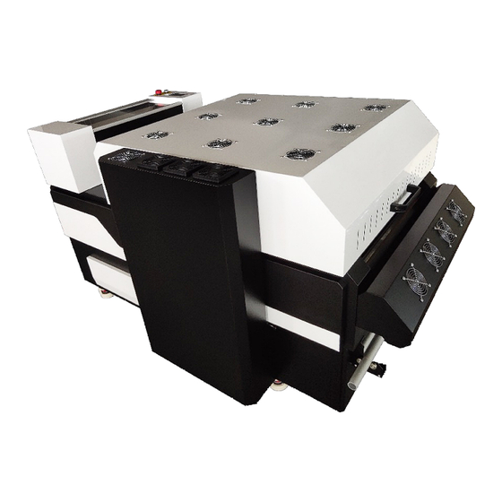
- Page 1 TX-Y6018P POWDER SHAKER User Manual 2020.06...
-
Page 2: Table Of Contents
Table of Contents FOREWARD........................3 About The Manual....................3 1. Safety Operating Instructionrs ................... 4 Brief Introduction....................4 Safety Symbols....................4 Warning and Precaution for Use................4 Installation Precautions..................5 2. Install Preperation ...................... 6 Machine Specifications..................6 Operating Conditions................... 6 Electrical connecton requirements............... 7 3. -
Page 3: Foreward
FOREWARD Congratulations on your purchase of TX-Y6018P Powder Shaker. Be sure to read this Operation Manual carefully and fully understand it before using the machine. Also, always keep this Operation Manual at hand and use it. About The Manual • This Operation Manual explains how to install, operate, maintain TX-Y6018P powder shaker. -
Page 4: Safety Operating Instructionrs
1. Safety Operating Instructions 1.1 Brief Introduction This Chapter introduces the important safety information. Please read and understand the safety information carefully before operating the machine. 1.2 Safety Symbols This caution symbol represents danger. Failure to observe the instructions given with this symbol can lead to serious injury to personnel and damage to the machine. -
Page 5: Installation Precautions
1.3 Warning and Precaution for Use Continued High Voltage Precaution to Avoid Personnel Shock or Fire • The machine should be grounded, according to the local safety electrical connection regulation. The ground voltage should be less than 3V. • Set the machine on smooth flat ceramic tile or ceramic ground. • Use specified anti-static floor mat to minimize harmful static build-up. -
Page 6: Install Preperation
• Machine requires forklift to remove from box. • Do not place anything on the installation site, and make sure that people do not approach the installation place. It may cause damage to the machine or personnel injury. 2.1 Machine Specification Model: TX-Y6018P Environment: Temperature: 18-30℃ (65-86 ºF) Humidity: 30-70% RH Power Consumption: Working mode: 5000W... -
Page 7: Electrical Connecton Requirements
Do Not Install the Machine in the Following Places: • A location near a fire • Places exposed to direct sunlight • Places subject to vibration • Places subject to extreme changes in temperature or humidity • Places near an air conditioner or a heater • Places where the machine may get wet • Places near a diazo copier that may generate ammonia gas • Places with poor ventilation • Unstable location 2.3 Electrical Connection Requirements... -
Page 8: Installation
3. Installation 3.1 Unpack Box Machine comes in wooden box (crate). 1. Unpack the crate and place 4pcs wooden/metal blacks under the wheels to lift the machine from the base. 2. Lift the machine from the gap between machine and base. Place in install space. 3.2 Connect Power 1. Using electrical cable that came with the machine. Please connect to the machine one side and another side to the power. - Page 9 NOTE: The machine must be well grounded.
- Page 10 3.3. Where to Install the Valve 1. Find the valve from the powder tray and install it into the hole that’s under the filtration.
-
Page 11: Names Of Parts And Functions
4. Names of Parts and Functions 4.1 Front of the Machine 1. Emergency stop switch. 2. Main power switch. 3. Powder spray box. 4. Media sensor (Belt move forward when film is detected) 5. Preheating plate 6. Cooling fans 7. Powder preheating lamp (inside) - Page 12 4.2 Powder Applicator and Shaker 8. Intelligent powder control system (Powder spray motor stop working when the powder reaches a certain weight) 9. Powder shake bar. 10. Rear feeding cylinder with vacuum...
-
Page 13: Back Of The Machine
4.3 Back of the Machine Vented oven lid Heating lamp Mesh belt vacuum and heating system Front feeding cylinder with vacuum Additional vacuum plate (Prevent film dropping) Tension take up system Material Cooling fans Zone filtration device Charcoal and HEPA filtration core Machine cooling fans Powder recycle tray... -
Page 14: Electrical Box
4.4 Electrical Box 110v main power inlet AC contactor Power supply PLC controller Heating controller Sensor and motor driver board Motor driver board... -
Page 15: Basic Operation
5. Basic Operation 5.1 Setting the Film Turn on the machine and load the film according to below diagram: • Once the printer has printed enough transfers to cover the front preheating board and the media extends to the first of two vacuum cylinders ensure that the PET transfer media is aligned correctly to inhibit any skew that may be present through the heating tunnel and take-up reel. •... -
Page 16: Main Panel Interface
5.2 Main Panel Interface... -
Page 17: Parameter Panel Interface
5.3 Parameter Panel Interface... - Page 18 5.3 Parameter Panel Interface Settings...
-
Page 19: Trouble Shooting
5.4 Trouble Shooting IO to check working condition of machine. - Page 20 5.4 Trouble Shooting - Check/Set Powder Dusting Function How to Set Powder Dusting Parameter 1. Principle of Powder Dusting Parameter: In the setting page. There is feed sensor para. Value – Current height value of the powder box position. iii. Up: height value when powder box doesn’t have enough powder.
-
Page 21: Maintenance
6. Maintenance • Switch on the waste oil valve and drain out the waste oil from the bottom of the filtration every 1-2 weeks. • Open the filtration gate first then open the vented oven lid and check if clean the waste oil around the cover every 1-2 weeks. • Change the Charcoal and HEPA filtration core every 6 months. • Empty the recycle powder trays and remove the powder dust every month. -
Page 22: Appendix 1: 2-Way Drive Board Informaition
Appendix 1: 2-Way Drive Board Information... -
Page 23: Appendix 2: 5-Way Drive Board Informaition
Appendix 2: 5-Way Drive Board Information... - Page 24 Appendix 3: 4-Way Step Motor Driver Board Information...
-
Page 25: Appendix 4: Plc Information
Appendix 4: PLC Information...
Need help?
Do you have a question about the TX-Y6018P and is the answer not in the manual?
Questions and answers