
Summary of Contents for Stemin MX12
- Page 1 MX12 USER INSTRUCTIONS ......38 Please read the manual before using the equipment!
-
Page 2: Table Of Contents
Shielded cables and I/O cords must be used for this equipment to comply with the relevant FCC regulations. Changes or modifications not expressly approved in writing by STEMIN GMBH may void the user’s authority to operate this equipment. This device complies with Part 15 of the FCC Rules. Operation is subject to the following two conditions: (1) this device may not cause harmful interference, and (2) this device must accept any interference received, including interference that may cause undesired operation. -
Page 3: Safety And Environment
• Use the unit only for the purposes described in these operating instructions. STEMIN GMBH will accept no liability for damage caused by incorrect handling or improper use. -
Page 4: Description
The device has a wide-range power supply unit and is connected to the mains using the mains cable supplied. In addition to many digital signal processing functions, the MX12 also has innovative automatic mixing functions. Up to ten MX12 can be cascaded if the twelve balanced inputs are not sufficient for your application. MX12... -
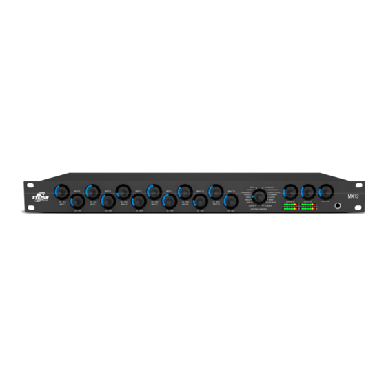
Page 5: Front Panel
These are labelled "IN 1" to "IN 12". Operating mode / system control The MX12 has a large number of functions, such as volume, treble ranges, bass, auto-mix functions, etc. The "SYSTEM CONTROL" rotary knob can be used to select these functions. -
Page 6: Rear Panel
The previous monitoring source is switched off by pressing on another source (switch between inputs and output). The output "REC (OUT)" cannot be monitored. Rear panel Figure 2: Rear panel of the MX12 Input channels 1-12 Gain control 1-12... - Page 7 The allocation of the individual channels to the asymmetrical stereo recording output can be configured as desired. Expansion/cascading connections Figure 8: EXPANSION Two RJ-45 sockets are provided for expansion/cascading. These are labelled with "IN - EXPANSION - OUT". MX12...
- Page 8 A phoenix terminal connects the case with the 0 V potential of the power supply. Only bridge the 0 V potential with the grounding (factory setting) or connect it to the central system ground, as otherwise the phantom power has no reference point and will not function. NOTE MX12...
- Page 9 Figure 13: Digital output The MX12 has a digital output which can be picked up via a balanced AES/EBU or an optical S/PDIF output on the rear panel of the device. The AES/EBU output can be accessed via a 3 pin Phoenix terminal.
-
Page 10: Automix Algorithm
Permanently present interfering signals, whose amplitude are large enough to be assessed as dominant, but whose level and frequency changes are too low, are not assessed as dominant. Interfering signals such as noise from fans and air-conditioning units are recognised and not used as activation criteria for microphone channels. MX12... -
Page 11: Installation And Connection
Mount the MX12 in your 19" rack. Rack mounting Cascading We recommend only using STEMIN GMBH accessory cables for cascading. NOTE The unit has two 100 MBit/s ethernet interfaces. These communicate the control data and audio between up to 10 units. This allows an automix system with up to 120 input channels, 40 output channels and 10 stereo headphone outputs to be established. -
Page 12: Connecting Microphones And Accessories
Connecting microphones and accessories Before connecting, read the operating instructions for your microphones and accessories. NOTE Connect microphones and accessories to the back of the MX12: Connect microphones and other signal sources (e.g. wireless microphone receivers) to the "IN" input channels. -
Page 13: Operation
A lower gain is recommended for microphones with a high output level. NOTE Turn the unit on at the power switch. The rotary knobs on the front panel of the MX12 are operated as follows: MX12 operation Figure 15: Operation of the rotary knob Turn the rotary knob clockwise or counter-clockwise to make changes to inputs and outputs and function settings. - Page 14 • Bass • Low Cut • Limiter • Compressor • Automixing • Priority • Pan / Balance • Delay • Routing to OUT 1 • Routing to OUT 2 • Routing to REC • Routing to DIGOUT • Equalizer MX12...
- Page 15 • Equalizer • Monitoring • Mute Stereo headphone output modes (output for monitoring) The "HEADPHONE" rotary knob is an exception. The stereo headphone output is always located in the "LEVEL" mode, regardless of the "SYSTEM CONTROL" rotary knob setting. MX12...
-
Page 16: Dsp Functions
The settings range from -∞ to +15 dB (acoustic feedback). The adjustment takes place in the appropriate increments. An LED illuminates at -∞, while the entire LED ring is illuminated at +15 dB and the acoustic feedback is no longer provided. Figure 19: Division of the LED ring for the LEVEL function MX12... - Page 17 The LED field illuminates as soon as the 0 dB level is reached (after the third click, see "Level" detail). VU function: The "SYSTEM CONTROL" rotary knob can be used to display the current audio level of the inputs, see MX12 operation. NOTE MX12...
- Page 18 More LEDs light up on the right side as the rotary knob is turned further to the right. Figure 23: Increments on the LED ring for the TREBLE function The adjustable increments are equal to 2 dB per click and also correspond to one LED. MX12...
- Page 19 All the input and output channels can be controlled in the "BASS" mode. Figure 26: Adjustment range for the function The "BASS" function raises or lowers the audio signal's bass range. The filter is designed as a first order bass shelving filter. The cut-off frequency is 100 Hz. MX12...
- Page 20 More LEDs light up on the right side as the rotary knob is turned further to the right. Figure 27: Increments on the LED ring for the BASS function The adjustable increments are equal to 2 dB per click and also correspond to one LED. Figure 28: Adjustment range for the BASS function MX12...
- Page 21 The settings range from 0 Hz (no effect) to 150 Hz (severe attenuation). One LED is illuminated at 0 Hz, while the entire LED ring is illuminated at 150 Hz. Figure 31: Increments on the LED ring for the LOW CUT function MX12...
- Page 22 The settings range from +20 dBu to -25 dBu. One LED is illuminated at +20 dBu, while the entire LED ring is illuminated at -25 dBu. Figure 34: Increments on the LED ring for the LIMITER function The adjustable increments are equal to 3 dB per click and also correspond to one LED. MX12...
- Page 23 All the input channels can be controlled in the "COMPRESSOR" mode. Figure 37: Adjustment range for the function The compressor ratio is fixed. It has a value of 1:2. Turning the rotary knob in a clockwise direction increases the effect, while turning it counter-clockwise dampens the effect. MX12...
- Page 24 LED ring is illuminated at -25 dBu. Figure 38: Increments on the LED ring for the COMPRESSOR function The adjustable increments are equal to 3 dB per click and also correspond to one LED. Figure 39: Adjustment range for the COMPRESSOR function MX12...
- Page 25 The automatic mixing function for the relevant channel is switched on by turning a rotary knob in the clockwise direction. (Entire LED ring is illuminated) Turning the rotary knob counter- clockwise switches the automatic mixing function off. (Only one LED is illuminated) Pressing the rotary knob also switches the function on or off. NOTE MX12...
- Page 26 Pressing the rotary knob also switches the function on or off. NOTE Switching on the "PRIORITY" function on an input channel turns off the function on the previously activated channel. This function can only be active on a single input channel. NOTE MX12...
- Page 27 In mono inputs, the signal is assigned equally to stereo left andright as standard. If the input is to be assigned to the left only , turn the rotary knob for the input to the left when the PAN function is active. MX12...
- Page 28 The settings range from 0 m to 75 m. One LED is illuminated at 0 m, while the entire LED ring is illuminated at 75 m. Figure 48: Increments on the LED ring for the DELAY function The adjustable increments are equal to 1 m per click. 5 m is equal to one LED. MX12...
- Page 29 (entire LED ring is illuminated). Turning the rotary knob counter-clockwise switches the function off (only one LED is illuminated). Pressing the rotary knob also switches the function on or off. NOTE Switching this on sets the input channel to the OUT 1 master bus. MX12...
- Page 30 (entire LED ring is illuminated). Turning the rotary knob counter-clockwise switches the function off (only one LED is illuminated). Pressing the rotary knob also switches the function on or off. NOTE Switching this on sets the input channel to the OUT 2 master bus. MX12...
- Page 31 (entire LED ring is illuminated). Turning the rotary knob counter-clockwise switches the function off (only one LED is illuminated). Pressing the rotary knob also switches the function on or off. NOTE Switching this on sets the input channel to the REC master bus. MX12...
- Page 32 (entire LED ring is illuminated). Turning the rotary knob counter-clockwise switches the function off (only one LED is illuminated). Pressing the rotary knob also switches the function on or off. NOTE Switching this on sets the input channel to the DIGOUT master bus. MX12...
- Page 33 More LEDs light up on the right side as the rotary knob is turned further to the right. Figure 59: Increments on the LED ring for the equalizer function The adjustable increments are equal to 2 dB per click or one LED. MX12...
- Page 34 The respective channel is switched to mute by briefly pushing the input or output rotary knob, with the exception of the "HEADPHONE" rotary knob. The MUTE function is indicated by the steady flashing of the LED ring. Another brief press or turn of the rotary knob removes the MUTE function. MX12...
- Page 35 Pressing the rotary knob of the desired channel (for more than 3 seconds) excludes the channel from the locking. Pressing the rotary knob again (for longer than 3 seconds!) relocks the channel. The set LOCK states are retained even after switching the MX12 off and on again! NOTE MX12...
- Page 36 The copy process can be performed in both directions. ("IN 1" to "IN 12" and "IN 12" to "IN 1") NOTE Figure 63: Select the rotary knob (source) Figure 64: Define the copy range (target) Figure 65: Hold down the rotary knobs Figure 66: Copy process complete MX12...
- Page 37 Wait until the automixer has completed its start sequence (approx. 15 seconds). Release the "SYSTEM CONTROL" rotary knob. The unit's factory settings have now been restored and a new system configuration can now be set up. Resetting the factory settings deletes all of the stored settings! NOTE MX12...
-
Page 38: Cleaning
Unplug the power supply cable from the socket. Clean the surface of the unit with a moistened (not wet) cloth. Never use caustic or scouring cleaners or cleaning agents containing alcohol or solvents, since these may damage the enamel and plastic parts. ATTENTION MX12... -
Page 39: Specifications
Digital analogue conversion for recording, monitoring and master output Data format: 24 bit Sample frequency: 48 kHz This product conforms to the standards listed in the Declaration of Conformity. To view a copy of the Declaration of Conformity for this product, visit http://www.Stemin.com or contact info@Stemin.com. MX12... -
Page 40: Troubleshooting
Distorted signal Volume control turned up too Turn down volume reproduction Input signal level too high Reduce input signal If the error persists despite these instructions, contact STEMIN GMBH GmbH or your STEMIN GMBH dealer immediately. MX12... - Page 42 STEMIN GmbH STEMIN GmbH Hauptstraße 25 D - 82549 Königsdorf Germany Telefon +49 8179 93110 Telefax +49 8179 931199 E-Mail info@stemin.com web www.stemin.com For other products and distributors worldwide visit www.stemin.com Technische Änderungen vorbehalten. Specifications subject to change without notice.
Need help?
Do you have a question about the MX12 and is the answer not in the manual?
Questions and answers