Advertisement
Quick Links
Advertisement

Summary of Contents for RHOMBUS DR40
- Page 1 DR40 Video Intercom User Manual Revision 1.0 230727...
-
Page 2: Table Of Contents
Contents System Overview Mounting Instructions Recommended Wiring Operation Registration Specifications Troubleshooting Appendix 2 DR40 User Manual... - Page 3 WARNING messages will be fully boxed as shown here. Failing to follow instruction may result in damage to the DR40 or other connected components. FCC Compliance Statement This equipment has been tested and found to comply with the limits for a Class A digital device, pursuant to part 15 of the FCC Rules.
-
Page 4: System Overview
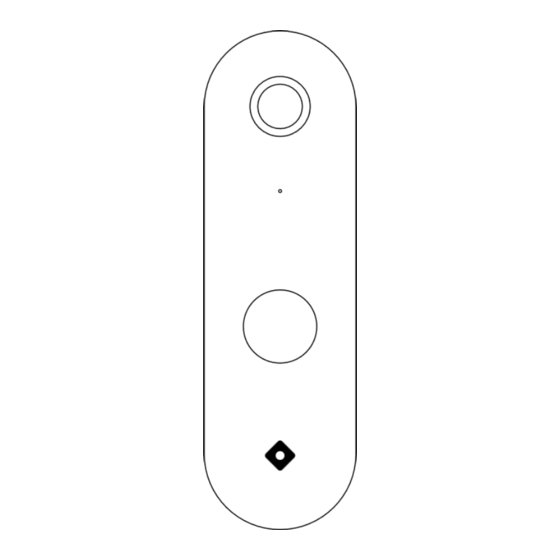
DR40 Overview Equipped with a door reader, camera, and intercom, the DR40 makes it easy to monitor entry events, grant access, and seamlessly communicate with visitors. Camera DR40 Video Reader Light Sensor Microphone IR LED (Internal) Button NFC Antenna Speaker Included in the Box: Tools You’ll Need:... -
Page 5: Mounting Instructions
Ensure that the tab at the top of the mounting bracket is inserted into the top slot of the DR40. STEP 4 While holding the DR40 in place, insert and tighten the T6 screw into the bottom of the bracket using the torx key provided. -
Page 6: Recommended Wiring
— Video Intercom If access control is not required, DR40 can be used as a standalone device to capture audio and video events. The DR40 can be powered using POE or a 12-28VDC, 12W power source. If powered remotely, the DR40 can connect to the network through ethernet or Wi-Fi. Use a CAT5 or CAT6 cable with RJ45 connector and plug into the DR40 pigtail cable for ethernet use. - Page 7 RS-485 RS-485 Power to the reader can be supplied using POE or a 12-28VDC external power source. DR40 has a maximum current rating of 791 mA at 12VDC, so should not be power directly by the DC20. Always check the power requirements of the door controller prior to installation. If PoE is not used, an Ethernet or Wi-Fi connection is required.
-
Page 8: Operation
Offline Mode During a network disconnection, the DR40 will continue to record and save the footage to the on board storage, while power is present. Access Control functionality is also preserved, however, user grants and schedules cannot be updated. Once the network connection has been restored, all alerts, movements, and access control configurations will be updated automatically. -
Page 9: Specifications
Dimensions: Mullion 50 mm x 165 mm x 35.1 mm [1.97 in x 6.5 in x 1.38 in] Weight: 0.40kg (0.9lbs) Mounting: Wood/drywall screws Included Credential Frequency: 13.56 MHz Credential Compatibility: Rhombus Badge, ISO 14443A (CSN), Rhombus Key app Connectivity/Power Controller Compatibility: DC20 Input Voltage: 802.3af or 11-28VDC Power Consumption MAX: 9.3W Environmental Operating Temperature: -40˚C to 50˚C [-40˚F to 122˚F]... -
Page 10: Troubleshooting
Troubleshooting Power Cycling If the DR40 needs to be power cycled, remove the reader from the mounting bracket and unplug the device from the power source. Leave unplugged for around 30 seconds before reconnecting. LED Indicators The DR40 LED will fade from white to “OFF”... -
Page 11: Appendix
Appendix Mounting Dimensions 1-3/8" (35 mm) " (83 mm) 1" (25.4 mm) DR40 User Manual... - Page 12 DR40 LED Ring Patterns Color Pattern Feedback Name Feedback Description White / OFF fade Starting Up Initial connection period, not yet fully available. Blue / OFF fade Unregistered Red / White fade ERR: No ACU RS485 connection is down. Blue / OFF, fast fade ERR: No network Unable to access the internet.
Need help?
Do you have a question about the DR40 and is the answer not in the manual?
Questions and answers