Table of Contents
Advertisement
Quick Links
Advertisement
Table of Contents

Summary of Contents for Intamsys FUNMAT PRO 610HT
- Page 1 User Manual FUNMAT PRO 610HT Large Scale∣High Temperature∣Industrial Production...
-
Page 2: Table Of Contents
Agenda 1 Service and Support ........................1 1.1 Service ............................ 1 1.2 Safety Information ........................1 1.2.1 Hazard Classification......................1 1.2.2 Potential Safety Hazard Area ................... 2 1.2.3 Operating State ....................... 3 1.2.4 Environmental Requirement ................... 3 2 Setup and Installation ........................4 2.1 General Information ....................... - Page 3 4.5.1 Nozzle Setting Interface ....................27 4.5.2 Material Library Configuration Interface ............... 28 4.6 System Interface ........................29 4.7 Other Interfaces ........................30 4.7.1 Remote Printing Interface ..................... 30 4.7.2 Wired Network IP Setting Interface ................31 4.7.3 Wireless Network IP Setting Interface ................32 5 Printer Operation .........................
- Page 4 5.7 Printer Status ........................58 5.7.1 Temperature and Humidity Status ................58 5.7.2 Filament Status ......................58 5.7.3 The State of the Liquid Cooling System ................. 58 5.7.4 Software Version ......................58 6 Leveling and Calibration ......................59 6.1 Trigger Distance Calibration ....................59 6.2 Automatic Leveling and XYZ Deviation Calibration ...............
- Page 5 Revisions and Editions Edition Date Description 2020.12 Initial edition Updated the chapters for preparations for equipment, leveling and calibration, safety control- 2022.03 related content, and illustrations of the user interface and equipment.
-
Page 6: Service And Support
3D printer (hereinafter referred to as “printer”, “equipment” or “machine”), as well as safety information and safety label locations. 1.1 Service Please contact INTAMSYS customer support for any problem not covered by this guide during your use of the printer. Region E-mail Tel. -
Page 7: Potential Safety Hazard Area
[Pinch warning]: The warning indicates that you may have a risk to pinch hand between two objects. There are one or multiple objects moving in your working area. 1.2.2 Potential Safety Hazard Area The following components and areas have been highlighted as potential safety hazards. Failure to follow safety procedures correctly can cause system failures or reliability issues. -
Page 8: Operating State
The Z-axis motion frame [Pinch warning] Warning: Do not wear ties, loose clothing or hanging accessories while working near moving components. [Anti-collision]: If there is a printed model on the platform, when the platform rises, pay attention to the height to prevent puncturing the organ type shield. -
Page 9: Setup And Installation
2 Setup and Installation This chapter describes the basic setup and installation of FUNMAT PRO 610 HT. 2.1 General Information 2.1.1 Attached Tools Please check the attached packing list (see appendix). These attached tools are common tools and spare parts for printer maintenance. Working Space Requirements for Installation 2.1.2 Check installation site preparation guide to ensure efficient and safe preparation of relevant... -
Page 10: Inspection Of The Printer Nameplate
Model mark: It lists the product name, printer model number and power requirements. This nameplate also lists the relevant certification information and INTAMSYS information. Serial number: Please provide the serial number listed in the nameplate to the INTAMSYS authorized partner or INTAMSYS when requesting service, so that the service personnel can quickly identify your printer configuration. -
Page 11: Equipment Reset
Such tools can be substituted as appropriate. Step 1: Please remove the screws on the wooden box with a manual electric drill equipped with 8 mm sleeve. Remove all the boards and remove the tape, foam and packing film from the machine. Use the ladder when working at height. - Page 12 Step 3: Confirm the port number of each cable on the power line, and connect the power supply according to the sequence of cables. The electrician or professional shall measure the phase sequence of power supply with a three-phase AC phase meter to ensure correct wiring. Connect the specified pins in turn according to the input.
- Page 13 Figure 2.7 Startup of equipment and unlocking of front door Step 6: Open the front door, take out the attached accessories (such as printing head cover, aggregate box, toolkit and printing plate), and make sure there is no debris in the chamber; Figure 2.8 Removal of attached accessories Step 7: Place the ladder on the left rear of the equipment, and open the rear top cover with the help of the ladder.
- Page 14 Step 8: Press the white "DP.ON" button to power on the XYZ axis. The button lights up in white; Figure 2.10 Power supply for the motion system Step 9: Click the "Axis" icon to enter the "MANU" interface, and click the "Home "...
-
Page 15: Filling And Discharge Of Coolant
Step 11: Connect the compressed air source with a φ10 quick connector (Note: Make sure that the compressed air supplied is clean and dry); Figure 2.13 Connection of compressed air Step 12: Add coolant for the equipment: Use a straight screwdriver to unscrew the cap at the coolant nozzle, insert the funnel, and fill coolant through the funnel. -
Page 16: Unlocking Of The Front Door When Powered-Off
2.2.4 Unlocking of the Front Door When Powered-off When the equipment is powered off, if the front door safety lock is locked, manually reset the safety lock. Step 1: Remove the sheet metal at the position of the front door safety lock; Step 2: Reset the mechanical lock function of the front door safety lock with a cross screwdriver or special tool, when the front door can be opened. -
Page 17: Printer Components
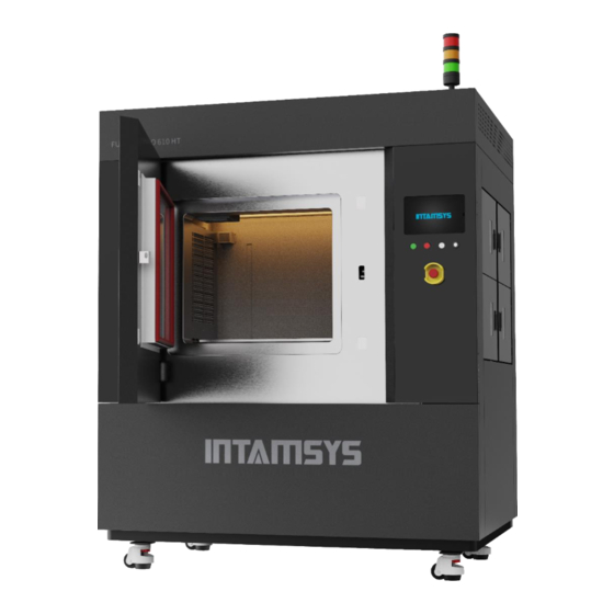
3 Printer Components This chapter describes the FUNMAT PRO 610 HT system components to help users better understand how the printer works and understand the functions of each core component. 3.1 Printer Abstract The visible part of the printer's appearance is shown in the figure below. Among them: the front panel of the right electric control cabinet, the left lower side panel and the rear side panel can be disassembled, and the top cover can be opened upward for the maintenance of internal components. -
Page 18: Printing Chamber Assembly
The user realizes the control of printing through the touch screen to get the machine status information. Switch button s are located at the bottom of the touch screen, including the white "DP.ON/Driver Power ON" button, the green "ON" button, the red "OFF" button, the key-shaped mode selector switch, and the red mushroom-shaped emergency stop button. -
Page 19: Filament Chamber
Inside handle Figure 3.6 Illustration of front door opening Figure 3.7 Printing chamber 3.4 Filament Chamber There are altogether four filament chambers, all of which are independent chamber. The filament spool is placed on the filament shaft and feeds filaments to the printing head for sample printing. When the filaments in the filament chamber are used up, the sensor attached on the auxiliary filament feeding wheel automatically detects this and exits the remaining filaments, and then the current filament chamber is switched to the spare chamber on the same side to automatically feed... -
Page 20: Printing Head
Filament chamber door sensor Light Heating device Auxiliary filament feeding device Filament shaft Figure 3.9 Interior drawing of filament chamber 3.5 Printing Head The printing head part is used to melt the filament and combine it with the motion of the XYZ axis to form the desired model on the printing plate. -
Page 21: Z Axis
3.7 Z Axis The Z-axis part drives the buildplate to move up and down. It can be repaired by removing the rear side plate. The trigger piece of the photoelectric sensor is already in the proper position, generally it does not need to be adjusted by the user. -
Page 22: User Interface
• System: The view of System parameters and related System Settings Click the status bar icon to perform the following actions: • INTAMSYS Information Query (INTAMSYS icon) • Open and lock operation (lock door icon) • Ethernet configuration (Wired network Link icon) •... -
Page 23: The Status Bar
Table 4.1 Icon status and click operation Icon Meaning Description and operation Icon Click to enter the profile page of INTAMSYS, and provide QR code, contact number and email Vacuum absorption status When the vacuum adsorption is on, click to... - Page 24 Remote printing status Gray is the closed status for the remote print service Blue is open for the remote printing service Blue and rotating for currently having The remote print The remote Remote user remote user access service print service access Click the icon to enter the remote Print service monitoring configuration interface.
-
Page 25: Navigation Bar
Figure 4.4 Status bar supplement 2 4.1.2 Navigation Bar The navigation bar is displayed on each home page of the user interface and provides single-touch access to the printer's Print, Tune, Axis, Material, and System functions. The user interface is broken down into multiple pages that contain related functionality. -
Page 26: Printing Interface
in this interface by default. • When you select the corresponding icon in the status bar, the interface will switch to the Settings or display interface related to the status • After selecting the corresponding function button in the navigation bar, the display interface will switch to the operation interface of the corresponding function module. -
Page 27: The Primary Status Interface
4.2.1 The Primary Status Interface Figure 4.7 Schematic Diagram of Main Status Interface Click the extension button to open/close the setup interface of preheating and heat maintaining in Figure 4.8. Preheating Temp maintaining selection selection Temp maintaining Preheating time time Change preheating Change temp time... -
Page 28: The Secondary Status Interface
Figure 4.9 Error prompt box interface 4.2.2 The Secondary Status Interface The secondary status interface displays the current temperature status of different components. The temperature display module is shown above the horizontal line as the current temperature, below the horizontal line as the target temperature, and the percentage at the lower right corner as the progress. -
Page 29: The Control Interface
4.2.3 The Control Interface The control interface is used to display printing progress and control printing, including open, start, pause, stop and other operations. The gear rotates when the print starts, and stops or pauses when the gear stops. Filament chamber Progress Time left temp... -
Page 30: Tune Interface
Command receiving and Enable log on/off sending display area Display temp data Display position data Clear display area Hide display area Figure 4.15 Log display area The Log display can be used to assist in troubleshooting. Note: Please cancel Enable log during printing, otherwise it may affect the printing speed and quality. -
Page 31: Axis Interface
4.4 Axis Interface The axis interface is used for manual operation of buildplate, print heads and extrusion and materials withdrawal. See Figure 4.17. Step length setting XY axis control area Nozzle control area Z axis control area XYZ return to zero Buildplate down to lowest point... -
Page 32: Nozzle Setting Interface
Left nozzle setting area Material unloading button Right nozzle setting area Auto-leveling calibration Nozzle change Nozzle cleaning Nozzle trigger distance calibration Material Library Configuration Material loading button Figure 4.18 Material Interface 4.5.1 Nozzle Setting Interface Figure 4.19 is the nozzle setting interface. Click the nozzle icon to switch the current nozzle. The nozzle setting interface can be used for material selection, nozzle temperature setting, material loading/unloading (see Section 5.2 of Chapter V) and other operations. -
Page 33: Material Library Configuration Interface
Figure 4.19 Nozzle Setting Interface 4.5.2 Material Library Configuration Interface The material library configuration interface is used for browsing the system material library and customizing the user material library. Material parameter display area Exit editing Material parameter setting area Operation buttons area Figure 4.20 Material Library Configuration Interface The material operation interface is used to edit materials. -
Page 34: System Interface
automatically saved. For material parameters added by the user, the user can click "Remove" to remove them or click "Change" to update them. 4.6 System Interface The system interface is used for system-related Settings, including system information viewing and upgrading, system-related parameter setting, printer system parameter setting, etc. Figure 4.21 System Interface Software Upgrade Operation Interface (SW Upgrade): ⚫... -
Page 35: Other Interfaces
Auto leveling enabled: Automatic leveling switch, blue for on, gray for off ⚫ Lock password enabled: Lock screen password switch, blue for on, gray for cancel. Click to enter the password change area. The default password is "intamsys" 4.7 Other Interfaces 4.7.1 Remote Printing Interface The remote printing interface is used to start the remote printing service, which can be entered by clicking the remote printing status icon in the status bar. -
Page 36: Wired Network Ip Setting Interface
Figure 4.24 Remote printing interface Note: Before using the remote printing service, the IP address needs to be configured successfully. Only one of wired or wireless network configuration IP can be selected. Currently, IP configuration of both networks is not supported at the same time. 4.7.2 Wired Network IP Setting Interface Figure 4.25 Wired network IP setting interface Click the wired network status icon in the status bar to enter the wired network IP setting interface... -
Page 37: Wireless Network Ip Setting Interface
Configuration area Ping test area Figure 4.26 Wired network IP setting interface After the IP address is configured, you can click the "Ping" button to test the connection between the printer and the gateway. Figure 4.27 shows the interface for testing the successful connection. Figure 4.27 Wired network IP setup test successful interface 4.7.3 Wireless Network IP Setting Interface The wireless Network (WIFI) IP setting interface is shown in Figure 4.28. - Page 38 Figure 4.28 Wireless network IP setting interface After entering the wireless network setting interface, click "Connect" button to enter the hotspot connection interface as shown in FIG. 4.29 and select WIFI hotspot. Figure 4.29 Hotspot connection interface Click the "Discover" button to find the WIFI hotspots that can be connected, select the hotspots that you want to connect, and then click the "Connect"...
- Page 39 Figure 4.30 Wireless network connection successful interface In Figure 4.31, select DHCP IP Address and click the "Set IP" button to get dynamic IP. Or select Static IP Address, Static IP mode, and then manually enter the IP address to be a Static IP. Figure 4.31 Wireless network dynamic IP address set successfully After successful configuration, you can also click the "Ping"...
- Page 40 Figure 4.32 Wireless network ping tests...
-
Page 41: Printer Operation
5 Printer Operation The chapter describes the basic steps for operating FUNMAT PRO 610 HT. 5.1 Basic user operation 5.1.1 Power on the Printer 1. First, confirm whether the air switch at the lower right of the equipment is closed. If not, push up the rotating operating handle to complete closing. -
Page 42: Turn Off The Printer Power
of boot. Figure 5.3 ON button and startup interface 5.1.2 Turn off the Printer Power Press the red shutdown button located at the bottom of the printer screen, and the screen prompts "Confirm shutdown". If you confirm shutdown and click the screen confirmation button, you will enter the shutdown process. - Page 43 1. Material chambers are located on the right side of the printer, divided into 4 independent chambers; 2. Turn the door handle to open the material chamber; Filament Filament Chamber 3 Chamber 1 Filament Filament Chamber 4 Chamber 2 Figure 5.4 Filament chambers 3.
- Page 44 Figure 5.5 Selection of printing materials on the Material Interface 5. Insert the material spool into the material shaft. The material coil should be in the upper outgoing line direction, that is, the tangential direction of outgoing line should be located in the lower part of the material shaft (see below figure), so as to ensure more smooth material loading.
-
Page 45: Unload The Material
Figure 5.7 Material loading 7. If the screen shows "Load Failed", close the dialog box first, then click "Set Temp" to keep the temperature, then long press "E↓" until the filament are ejected from the nozzle; Or close the dialog box, and then click the "Load" button again to repeat the operation and try to Load the material again. -
Page 46: Edit The Material
Step4: Retracting completed. Please take out the material. The material unloading process will be completed in 2min. Figure 5.8 Material unloading 3. Open the material chamber, take out the filament roll, and rewind the 2 m exiting filament onto the filament spool. To prevent entanglement the next time you use the unloaded material, be sure to insert one end of the filament into a hole in the side of the coil. -
Page 47: Change Nozzles And Clean Nozzles
Figure 5.9 Material parameter editing The material operation interface is used to edit materials. The material parameters display interface shows all materials. Other materials can be displayed by sliding up and down. The built- in parameters of the printer cannot be edited, changed, or deleted. However, the user can select the corresponding material parameter column and click "New"... - Page 48 2. Click the "Change nozzle" button in the lower right corner of the screen. The printing buildplate will move to the lowest position, and the printing head will move to the middle position of the chamber. Follow the on-screen instructions step by step. 3.
- Page 49 5. After the nozzle reaches the target temperature, loosen the screws on the front and side of the fan cover with 2.5 mm inner hexagon wrench and remove the fan cover. Then loosen the 2 fixing screws on the heating block and take out the nozzle. Fan cover fastening screws Heating block fixing screws Nozzle kit...
- Page 50 7. Click the 'Next' button to complete the nozzle installation, or click the 'Change Another' button to Change the nozzle of the other printing head as indicated. Fastening screw Nozzle kit Figure 5.12 Illustration of fixing of new nozzle 8. Install the printing head cover and set the diameters of the left and right nozzle respectively on the screen.
-
Page 51: Clean Nozzles
Note: After changing the nozzle, Z offset calibration, printing head height difference calibration, automatic adjustment and XY offset calibration must be implemented in turn to ensure normal printing. 5.3.2 Clean Nozzles The cleanliness of the nozzle directly affects the accuracy of calibration and automatic leveling, and also affects the quality of printing. - Page 52 to room temperature. Each stage requires the nozzle to be cleaned.
-
Page 53: Change The Material
Note: For the leveling and calibration steps, the cleanliness of the nozzle is required to be extremely high. After cleaning the nozzle, there must be no residual material at the tip of the nozzle. 5.4 Change the Material 5.4.1 Change the Material before Printing If the type of Material needs to be changed before printing, in addition to changing the Material at the "Material"... -
Page 54: Replenish Material After Missing Material Alarm
stop printing and move to the default position for material changing; 2. Unload old materials. Refer to 5.2.2 for detailed steps; 3. Install and load new materials. Refer to 5.2.1 for detailed steps; 4. The material loading is finished, click the "Start" button in the interface of "Print" to continue printing. -
Page 55: Import Printing File Into Printer
directly without any gluing on the surface. Please select the correct type of buildsheet according to the type of printing materials. The print buildsheet can be reused without any damage. In particular, the reused print buildsheet should be cleaned of the remaining print materials. Buildsheet type Applicable printing materials PC board... -
Page 56: Import The Printing File
Figure 5.15 Import printing file through FTP network 5.5.3 Import the Printing File 1. First select the location of the print file. Select the location of your files, such as U disk (USB) or File Transfer Protocol (FTP), from the drop-down bar in the upper right corner of the screen. 2. -
Page 57: The Setting Of Printing Parameters
preheating time of the left nozzle material set on the Material Interface of the printer (because the material is different from that in the Gcode, it is necessary to confirm whether the material setting on the Material Interface is consistent with that in Gcode). When the platform temperature and chamber temperature are close to the target value, start the preheating timing;... -
Page 58: Printing Alarm
2. Click "-"/" + "on the right side or rotate the knob below to modify the parameter value, and the specific value will be displayed in the box; 3. Click Set button to complete the setting of this parameter. Figure 5.18 Setting of printing parameters 5.5.6 Printing Alarm If the printer detects a fault that could affect the print, a warning is given on the display. -
Page 59: Terminate Printing
2. After the path in the cache is completed, the Z-axis platform decreases slightly, the nozzle stays in place and stops heating, and the chamber temperature remains unchanged; 3. To resume printing, press the start button in the interface of Print. The recovery command is sent to the printer instructing it to resume printing. -
Page 60: Change Printer Default Settings
5.6 Change printer default Settings Figure 5.18 System parameter settings of the printer 5.6.1 Modify the System Date and Time The system time of the printer will not be updated according to the local time zone, so it needs to be modified by the user. -
Page 61: Turn On/Off Usb Print Mode
5.6.4 Turn on/off USB Print Mode USB Print enabled (USB Print mode), which enables remote serial port direct printing through the USB serial port on the smart panel. In the case of enabling, the motherboard will interrupt communication with the screen and switch to USB serial port device communication. It is used for external computers to directly connect the printer with USB serial port for printing. -
Page 62: Liquid Cooler Control
Click the right side button to turn on/off Lock Password enabled function on the System interface, and the blue color shown is the activation. Click to enter the password modification interface. The default password is "intamsys". -
Page 63: Printer Status
5.7 Printer Status 5.7.1 Temperature and Humidity Status The temperature and humidity status of the printer can be viewed in real time on the Print interface. L: The target temperature and real-time temperature of the left nozzle; R: The target temperature and real-time temperature of the right nozzle; C: The target temperature and real-time temperature of the chamber;... -
Page 64: Leveling And Calibration
SW version: Screen version; FW version: Firmware version. 6 Leveling and Calibration This chapter describes the leveling and calibration method for operating FUNMAT PRO 610 HT. 6.1 Trigger Distance Calibration The leveling sensor is mounted on the right printing head, and the accuracy of its trigger distance calibration directly affects the accuracy of automatic leveling. - Page 65 3. Operate as the guide on the screen. Place the feeler between the nozzle and the glass of the printing platform (thickness: 0.2mm). Click the coarse adjustment button "Z↑0.05"/" Z↓0.05 " or fine adjustment button "Z↑0.01"/" Z↓0.01 " on the screen to adjust the rise/fall of the Z-axis so that the distance between the nozzle and the glass of the platform is just enough to fill the feeler;...
-
Page 66: Automatic Leveling And Xyz Deviation Calibration
6.2 Automatic Leveling and XYZ Deviation Calibration In the Material interface, click the "Balance" button to enter the automatic adjustment and XYZ offset calibration interface. The three steps from left to right are Z Calibrate, Leveling and XY calibrate. Any one or more of these steps can be performed optionally, but the three steps from left to right must be performed sequentially, and unnecessary steps can be clicked on the Skip button below the icon. - Page 67 in the Z direction. Please take out the special z-offset calibration dial indicator equipped with the machine and perform calibration according to the prompts on the screen. 1. Click the Z calibrate (Z Offset Calibration) icon, a prompt box will pop up to prompt cleaning the printing platform.
-
Page 68: Automatic Leveling
4. After calibration, take out the dial indicator and close it. 6.2.2 Automatic Leveling Automatic leveling is mainly used to measure the position of three points on the platform by means of a leveling sensor mounted on the right printing head. The printer determines the relative position of the printing buildsheet and XY motion plane by itself, and compensates the rise or fall of z-axis in real time during printing. - Page 69 1. Click the icon of Leveling, a prompt box will pop up to prompt the cleaning of the printing platform, chamber and nozzle to prevent interference with Leveling. If it has been cleaned up, click "OK" button to officially enter the automatic leveling operation; 2.
-
Page 70: Xy Offset Calibration
4. When in automatic adjustment, the nozzle will detect 3 points on the platform. After completion, the screen prompts automatic leveling success. It will also prompt you to clean the chamber. If you have finished cleaning, click Finish. The platform will drop to the bottom of the chamber and then return. - Page 71 1. Click XY Calibrate (XY offset calibration) icon, prompt to confirm whether the material of left and right printing heads has been loaded, and prompt to clean the printing buildplate. Click Print button to start the calibration model printing. (If the XY deviation value is known, no need to click Print button, directly click Skip button, and then enter the X offset value and Y offset value respectively);...
-
Page 72: Material Weight Calibration
(4) Enter the "N" value in the input box. The Y offset value should be obtained by reading the numerical direction scale, as follows: (1) Take the model printed by the left nozzle as the reference, and read the model scale printed by the right nozzle;... - Page 73 material spool and material. In order to obtain the accurate weight of material, the weight of material shaft and material spool needs to be deducted. The weight calibration steps of materials in the filament chamber are as follows: 1. On the System interface, click The Weight Calibration button to pop up the calibration box. 2.
-
Page 74: Maintenance
7 Maintenance Correct and regular maintenance will not only prolong the service life of the machine, but also greatly improve your printing success rate and printing effectiveness each time. Maintenance tasks must be performed on a regular basis to ensure that the system is in optimum working condition. This chapter describes the various maintenance tasks that users need to implement on FUNMAT PRO 610 HT. -
Page 75: Clean The Buildsheet
Vacuum hole Vacuum groove Figure 7.1 Vacuum platform cleaning 7.1.2 Clean the Buildsheet Use a tool such as spatula to separate the model from the print buildsheet. The remaining materials on the buildsheet or the materials dropped during the printing process should be cleaned in time before each printing to avoid affecting the next printing. -
Page 76: Clean The Printing Chamber
Figure 7.3 Collection box cleaning 7.1.5 Clean the Printing Chamber Check and clean the printing chamber, and remove the remaining debris and residue. 7.2 Weekly Maintenance Clean Printing Chamber Interior 7.2.1 Use a vacuum cleaner and a sharp knife to clean the waste and residue in the buildplate, the bottom of the chamber, etc. -
Page 77: Clean Up The Filament Chamber
housing clearance, it is necessary to remove the housing for cleaning. Hold the printing head cover with one hand, open the spring clasp with the other hand, and remove the printing head cover. According to the situation of material penetration, use tools to clean. Buckle Nozzle The system will automatically use the nozzle cleaning unit to clean the nozzle before and... -
Page 78: Ball Screw And Guide Rail Cleaning
7.3.2 Ball Screw and Guide Rail Cleaning Good lubrication is very necessary when using ball screw and guide rail. Without sufficient lubrication, the friction between steel ball and rolling surface will increase during operation, which may shorten the life of the screw. Therefore, it needs to be maintained regularly. The equipment needs to be maintained in three places: XYZ axis, see the figure below. -
Page 79: Annual Maintenance
After repeated operation for many times, apply high temperature grease on the surface of ball screw and guide rail to protect the surface of screw guide rail. • Note: The guide rail of the X and Z axis uses the C-Lube series of IKO, which is generally used once every 6 months, so the quarterly equipment is frequently used, it is recommended to add grease once every 3 months. -
Page 80: Replace The Coolant
Please be aware of safety. The latest versions of machine firmware and screen software are available at: https://www.intamsys.com/ Note: ⚫ Do not use rough or highly alkaline products. -
Page 81: Troubleshooting
8 Troubleshooting This chapter lists some of the types of failures that can occur during the printing process and the troubleshooting measures required after each failure occurs. If you have any problems following this user manual, please contact customer support in your area. Fault Error Name Error Type... - Page 82 Please try to switch the nozzle. If the error still exists, Nozzle1 limitation exception warning check the nozzle limit sensor and the clamping condition of filament Please try to switch the nozzle. If the error still exists, Nozzle2 limitation exception warning check the nozzle limit sensor and the clamping condition of filament...
- Page 83 Filament chamber3 door is open remind Please close the filament chamber door Filament chamber4 door is open remind Please close the filament chamber door Vacuum is low warning Please check the vacuum pipeline Check the filament chamber temperature sensor and Filament chamber T too low remind wiring...
- Page 84 Mismatch of received command line Please try to resume printing or give up printing after warning numbers pausing Please check whether there is interference in the 24V Serious mismatch of received command error power supply or whether the main board is working line numbers normally...
-
Page 85: Appendix Operating Instructions For Standard Parts
Appendix Operating instructions for standard parts 1. Cooling Unit 1.1 Display Screen Configuration 1. The main contents of the display screen are shown as the following figure, including work indication, stop indication, fault indication, heating indication, refrigeration indication, setting temperature, measured temperature, and real-time speed of the compressor. Work indication: When the light is on, it means that the chiller is in startup state (AUTO indicator is on);... - Page 86 2. The display adopts capacitive touch buttons. Their main functions include switching machine operation and setting the water temperature in the water tank. The buzzer will emit a short "beep" sound when the button touch is effective, and will not respond when the button touch is invalid.
- Page 87 and the minimum value will be 0℃. When clicking the button on the "SET F2" interface, the low temperature alarm temperature difference will decrease by 0.1℃. Long press it for more than 2 seconds, the low temperature alarm temperature will decrease continuously, and the minimum value will be 0℃.
-
Page 88: Vacuum/Air Pressure Gauge
2. Vacuum/Air Pressure Gauge Unit display Main screen Status indicator1 Secondary Screen Status indicator2 DOWN Model switch 2.1 Setting description Setting Item Initial Status Description Compare output 4 Set the output mode to compare mode 1 output mode Settings Compare output 2 output mode Settings Set the output mode to compare mode 2 (Standard type only) - Page 89 2.2 Air Pressure Related Setting The air pressure gauge displays the intake pressure, and adjust the three keys of MODE, UP and DOWN to set it: Step 1: Menu Settings Hold for 2 seconds OUT1 OUT1 set as EASY configuration Single click OUT2 set as OFF OUT2...
- Page 90 2.3 Vacuum Meter Related Settings The vacuum gauge displays the vacuum degree when the buildsheet is absorbed. Adjust the three keys of MODE, UP and DOWN for setting: Step 1: Menu Settings Hold for 2 seconds OUT1 set as EASY OUT1 configuration Single click...
- Page 91 Xiupu Road, Shanghai, China Ostfildern Deutschland Eden Prairie, MN 55344 Copyright ©2022 INTAMSYS Technology. All rights reserved. The information at hand is provided as available at the time of printing, INTAMSYS reserves the right to change any information without updating this publication.
Need help?
Do you have a question about the FUNMAT PRO 610HT and is the answer not in the manual?
Questions and answers