Table of Contents
Advertisement
Quick Links
Advertisement
Table of Contents

Summary of Contents for BigBattery TITANGREEN EP18K-Li
-
Page 2: Table Of Contents
Table of Contents 1. External view and technical parameter ..................4 2. Safe driving, operation and maintenance of forklift ..............6 2.1 Transportation,loading,unloading and lifting of forklifts ........... 7 2.1.1 Forklift transportation ...................... 7 2.1.2 Forklift loading and unloading ..................7 2.1.3 Lifting of forklifts ...................... - Page 3 5.1 Summary ........................... 61 5.2 Operating environmental conditions ................. 62 5.3 Routine inspection and maintenance of AC motor ............62 6. Lithium battery and charger ....................62 6.1 Use and maintenance of lithium battery ................62 6.1.1 Instructions for use of lithium battery ................62 6.1.2 Charging steps and precautions of lithium battery ............
-
Page 4: External View And Technical Parameter
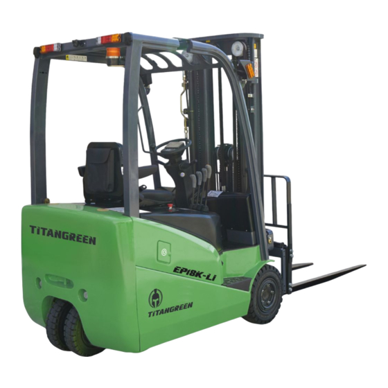
1. External view and technical parameter Outline drawing of three-wheel lithium battery forklift... - Page 5 Performance parameters of three-wheel lithium battery forklift Manufacturer TITANGREEN Model designation 1.8T Power Electric Operation Rated capacity lb(kg) 3968(1800) Load center in(mm) 24(610) Tire type-cushion, solid, pneumatic, etc. Drive/steer solid/solid Tire size Drive/steer 18X7-8/15×4.5-8 Wheels - number X=driven Drive/steer 2X/2 Tread Tires Std dr/steer in(mm)
-
Page 6: Safe Driving, Operation And Maintenance Of Forklift
2. Safe driving, operation and maintenance of forklift Forklift drivers and managers must remember "safety first". Before the first operation, please carefully read the Operation and Maintenance Manual, which will enable you to fully understand our forklift and operate it correctly and safely. 2.1 Transportation,loading,unloading and lifting of forklifts 2.1.1 Forklift transportation (1)When the forklift is transported by container or truck, the parking brake pedal shall... -
Page 7: Parking Of Forklifts
Notice: Dismantling and slinging the component shall not be performed without the approval of our company. Under special circumstances, the appointed sling position should be used. The balance weight, fork and mast of the forklift truck all have their appointed sling position.The above weights are for reference only and may be adjusted due to different counterweights or technical optimization. -
Page 8: Precautions For Safe Operation
(6)Check the hydraulic oil and brake fluid for leakage. (7)Check the tightness of the main fasteners. (8)Check whether the lighting and signal are normal. (9)Release the parking brake. ( 10 ) Carry out the trial operation of mast lifting, forward and backward tilting, forklift steering and braking. - Page 9 additional instructions we provide for you and use them strictly according to the requirements. Users are not allowed to modify without permission. ( 9 ) Do not use a fork to pull the embedded object (if necessary, the pulling force shall be calculated first).
- Page 10 cargo lifting or lowering should not be too fast. ( 20 ) Before tilting the mast forward and backward, the forklift shall be braked, and shall tilt slowly when tilting forward to prevent the goods from slipping out suddenly. 21 ) Tilt the mast of the high lift forklift truck as backward as possible when operating the truck.
- Page 11 ( 33 ) Start, turn, drive, brake and stop carefully, especially when turning on wet or smooth roads. ( 34 ) It is forbidden to suddenly start, accelerate, stop and turn the forklift. Improper operation may cause the forklift to roll over. If this happens, the driver should keep calm and avoid jumping.
-
Page 12: Maintenance Of Lithium Battery Forklift
the requirements of the load curve. Within the specified load center, its bearing capacity is the same as that of the standard fork. When the load center moves forward, the load must be lowered; It is strictly forbidden to lift or hit the goods with the fork tip. Pay special attention to safety when driving or turning. -
Page 13: Maintenance Summary
( 5 ) Instruments and lighting fixtures: check whether the instruments, lighting, connectors, switches and electrical circuits work normally. 2.5.3 Maintenance Summary (1)Forklifts need to replace some key safety parts regularly. Please use our pure parts. (2)The same type of oil must be used when replacing or refueling. 3 )... -
Page 14: Forklift Oil And Grease
Note: During maintenance and inspection, it is not allowed to use the forklift body as a step or the mast and shelf as a ladder. This is very dangerous. Unsafe actions may lead to serious accidents. 2.5.4 Forklift oil and grease Name Brand and code Note... -
Page 15: Brief Operating Instructions
2.6 Brief operating instructions 2.6.1 Control mechanism and instrument Function and use status of control mechanism Name Function Usage status Step to the bottom to realize braking Parking brake control Realize forklift parking brake function Change the driving direction of Push forward, reverse backward,median shift knob the forklift... -
Page 16: Brief Description Of Operation
pedal brake Brake forklift Press the brake Used operate the two Centralized light and Move the combination switch forward to position light control and turn turn signal switch turn left and backward to turn right. signal switch Step down and accelerate The controller outputs the corresponding speed according to the amplitude of the Accelerator pedal... -
Page 17: Maintenance Of Control System
Light control switch: The switch has two positions. The switch rotates at different positions, and the lamp lights up as shown below. Lamp name Phase 1 Phase 2 headlamps ----- Side marker lamp (2) Turn signal: pull the turn signal switch backward, the front small light and rear upper and lower combination light turn signal lights on the right side of the forklift are on, and push the turn signal switch forward, the front small light and rear upper and lower combination light turn signal lights on the left side of the forklift are on, and the corresponding instrument turn... -
Page 18: Special Reminder
Cables shall be checked every three months. ( 4 ) Check the spring of the pedal or handle. Ensure that the spring can deform normally and return to its original position. Check every three months. ( 5 ) Check the movement of the contactor. The contact of the contactor should move freely to ensure that the contact is not bonded. -
Page 19: Warning Sign
2.7 Warning sign The warning board affixed to the vehicle is used to explain the use methods and precautions of the vehicle. Please read carefully before driving. This is for your sake as well as for the vehicle. If the warning sign falls off, please re attach it immediately. After repair and maintenance, please check whether the nameplate is complete and the handwriting is clear. - Page 20 (2)General information when operating (3)Lubrication system...
- Page 21 (4)Tipping safety sign (5)Hood clamp label (6)Tipping safety sign...
- Page 22 (7)Safe driving sticker (8)Do not enter the space behind the mast (9)Lifting point indication...
- Page 23 (10)No manned sign (11)Lifting sign...
- Page 24 (12)Pay attention to the warning sign of injured hands (13) Load curve diagram...
-
Page 25: Structure, Principle, Adjustment And Maintenance Of Lithium Battery Forklift
3. Structure, principle, adjustment and maintenance of lithium battery forklift 3.1 drive system 3.1.1 Summary The drive system of the three-wheel forklift truck includes two parts: the traditional transmission system and part of the braking system. The dual-motor drive structure of the front wheel makes the left and right front wheels of the three-wheel forklift independently own the drive axle, gearbox, brake and drive motor, which greatly improves the working efficiency. - Page 26 01.Hexagon bolt 14.planet gear 28.helical gear 02.Cylindrical pin 15.Grooved nut 29.pinion 03.Circlip 16.Gamma 30.Shaft seal 04.Needle sleeve 17.Bolt plug 31.Cylindrical pin 05.Sealing gasket 18.Inner circle support 32.Outer brake friction plate 06.Shaft cover 20.Installation disk 33.Inner brake friction plate 07.Tapered roller bearing 21.Planetary support 34.Tank cover 08.Pressure spring...
-
Page 27: Removal Of Drive System
3.1.1.2 Front wheel assembly The front wheel assembly is composed of solid tires and rims. The models of front wheel tyres and rims are as follows: Solid tires: 18 × 7-8 OD × Width=457 × 170(mm) Rim: 4.33R 3.1.2 Removal of drive system Before carefully disassembling the gearbox, remove the front wheel assembly and traveling motor connected to it before repairing and maintaining the parts in the gearbox. -
Page 28: Installation Of Transmission System
3.1.2.3 Removal of transmission Generally, do not disassemble the gearbox. If there is any problem, please contact our dealer. 3.1.3 Installation of transmission system 3.1.3.1 Installation of traveling motor Before installation, clean and dry the mating surface of the gearbox and motor with detergent (such as loctite706 or alcohol), and check whether the mating surface is damaged. - Page 29 3.1.3.2 Install the transmission on the frame (Fig. 1-6) Check whether the connecting plate surface of the frame is flat or damaged, and the flatness of the plane of the transmission installation is not greater than 0.1mm. Fix the transmission to the frame with seven M14 hexagon-head bolts, and the tightening torque is 135 There is an oil inlet and an oil outlet under the transmission bracket.
-
Page 30: Addition Of Gear Oil
3.1.4 Addition of gear oil The service cycle of gear oil is 1000 hours/year (whichever comes first), that is, the gear oil needs to be replaced after the forklift works for 1000 hours or one year. Drain the gear oil in the reducer and add the specified gear oil. -
Page 31: Braking System
(f) Tighten the oil filler plug with sealing ring, and the tightening torque is 22Nm, as shown in Fig. 1-8. 3.2. braking system 3.2.1 Summary The brake system is composed of brake pedal, brake master cylinder and oil-cooled lubricating brake. This oil-bath multi-friction disc brake is installed in the reduction box, which eliminates external pollution, greatly extends the service life of the brake and reduces the use and maintenance costs. - Page 32 3.2.1.2 brake master cylinder The master cylinder consists of a valve seat, a check valve, a return spring, a leather cup, a piston and an auxiliary leather cup.(see fig 2-2) The end is fixed with a stop washer and a stop steel wire, and the outside is protected by a rubber dust cover.
- Page 33 3.2.1.3 Connection between brake system and drive unit There are two mechanical interfaces at the connection between the drive unit and the brake, one for the service brake oil pipe and the other for the bleeding of the service brake system, as shown in Figure 2-3.
-
Page 34: Maintenance And Adjustment Essentials Of Brake System
3.2.1.6 Brake system operation After the installation and commissioning of the service brake and parking brake, the normal service brake is achieved by pressing the brake pedal; The parking brake handle is placed on the left side of the instrument rack, and is meshed with the disc brake in the drive unit through the brake cable. -
Page 35: Steering System
(b)Adjust the stop bolt to make the brake pedal height appropriate; (c)Step down the brake pedal and lengthen the push rod until the front end of the pushrod contacts the master cylinder piston; (d)Tighten the push rod lock nut. 3.2.2.3 Brake switch adjustment (Fig. 2-4) (a)Loosen the brake lock nut after the brake pedal height is adjusted;... - Page 36 3.3.1.1 Steering wheel The forklift steering wheel is operated in the same way as usual, that is, when the steering wheel rotates to the right, the forklift turns to the right, and when the steering wheel rotates to the left, the forklift turns to the left. The steering wheel is installed at the rear of the forklift, which enables the rear of the forklift to swing outward during steering.
- Page 37 Figure 3-2 Working principle of load sensing steering system...
-
Page 38: Adjustment And Maintenance Essentials
3.3.1.3 Steering device The steering device (as shown in Figure 3-3) is composed of steering cylinder, steering axle body, steering wheel and other components. The steering cylinder drives the steering axle body to rotate, and the steering wheel rotates with the steering axle body. The wheel is pried onto the rear hub through the rim, and the rear hub is installed on the steering axle body through two tapered roller bearings. - Page 39 ( f ) Then gently tap the hub with a wooden hammer, turn the hub 3-4 times by hand to ensure smooth rotation, and measure the rotation torque of the hub, which is 2.94-7.8N. m (0.3-0.8kg · m); ( g ) When the rotational torque is higher than the specified value, it can be returned by 1/6 turn, and then its rotational torque can be measured;...
- Page 40 3.3.2.3 Steering system fault diagnosis Problem Cause analysis Exclusion method The oil pump is damaged or faulty Replace Steering wheel does rotate The rubber hose or connector is damaged, or the pipe is blocked Replace or clean Pressure of safety valve is too low Adjust pressure There is air in the oil circuit Exhaust air...
-
Page 41: Electrical System
4. Electrical system 4.1 Summary The electrical system is mainly composed of lithium battery, walking motor, oil pump motor, multi-function integrated electronic control assembly, control switch, instrument and lighting devices. Fig 4-1 Electrical system structure diagram... - Page 42 LED three-color tail light (short Intelligent instrument assembly line) microswitch Reverse image camera LED three-color tail light (long The reverse buzzer line) Horn brake light switch Parking brake switch warning light 40mm emergency stop switch Working light Turn signal with width indicator contactor Fuse box assembly Control box assembly...
- Page 43 Figure 4-2 Schematic diagram of electrical system...
-
Page 44: Instrument
4.2 Instrument 4.2.1 Summary The AC three-wheel forklift adopts the LCD color screen combination instrument and uses the high-definition LCD display screen for real-time display. The instrument is connected with battery and electric control via CAN line. 4.2.2 Instrument interface Instrument interface description DISPLAY TYPE TECHNICAL DESCRIPTION... -
Page 45: Instrument Instructions
SOC display E/S/H Mode Running time 4.2.3 Instrument instructions Function Note Logo The green icon flashes when turning left is Left turn indicator enabled Seat indicator Yellow icon when leaving the seat Parking brake indicator Red icon when parking brake icon Work light icon indicator Display whether the work light is working... - Page 46 When there is an alarm, the alarm text is displayed. For example: “BMS:XXX” “Travel controller:XXX” “Oil pump controller:XXX” Pointer scale display, red value display Battery level display when less than 10% Three operating modes E, S and H are Operating mode displayed, and E mode is the default when power on Running time...
-
Page 47: Instrument Working Process And Instructions
Select button to the left Right selection button Select button down Menu button Back button confirm button 4.2.4 Instrument working process and instructions 4.2.4.1 One button start function description (1)Check before power on: 1 、 The lithium battery discharge plug and the vehicle discharge plug are fully and firmly inserted;... - Page 48 initialization, and automatically displays the main working interface. The main interface displays various parameters of the current machine, such as high and low beam lamps, left and right turn signals, position lights, seat indicators, foot brake indicators, power battery voltage, power battery current, battery SOC, driving speed, gear indicator, working mode, time indicator, etc.
- Page 49 ( 1 ) Press the menu key on the main interface to enter the main menu, including controller parameters, BMS information parameters, vehicle setting parameters and version information parameters, as shown in the following figure: (2)Enter the control parameters in the main menu, as shown below:...
- Page 50 The specific values of 10 parameters including running time, traveling motor speed, traveling motor current, traveling motor temperature, traveling controller temperature, oil pump motor speed, oil pump motor current, oil pump motor temperature, oil pump motor controller temperature and controller fault code are displayed. (3)Enter BMS parameters in the main menu, as shown below:...
- Page 51 Display the specific values of 12 parameters, including total battery voltage, total battery current, SOC, cell max. voltage, cell # of max. voltage, cell min. voltage, cell # of min. voltage, cell max. temp, cell # of max. temp, cell min. temp, cell # of min. temp and battery pack charged times.
-
Page 52: Matters Needing Attention
Two parameters are displayed: reversing image and automatic power-off. The reversing image switch can be set in the reversing image option, and the automatic power-off time can be set in the automatic power-off time option. (5)Enter version information in vehicle main menu, as shown below: Display control box software version and instrument software version parameters. -
Page 53: Controller Structure
4.3.2 Controller structure... -
Page 54: Controller Fault Code
4.3.3 Controller fault code 20 ERROR Accelerator pedal switch activated during startup 21 ERROR Direction switch activated during startup 22 ERROR Simultaneous activation of front and rear direction switches 23 ERRORAccelerator pedal analog value out of range 24 ERROR Accelerator pedal analog fault 31 ERROR Driver CAN communication failure 32 ERRORLow battery voltage 34 ERROR CPU internal error... - Page 55 98 WARNING Traction driver overcurrent or short circuit 101 ERROR Short circuit of traction motor driver 102 ERROR High temperature of traction drive 103 ERROR High temperature of traction motor 104 ERROR Traction drive overcurrent 105 ERROR Traction driver pre charging timeout 110 ERROR Low DC bus voltage of traction driver 111 ERROR High DC bus voltage of traction drive 112 ERROR High DC bus voltage of traction drive (hardware monitoring)
-
Page 56: Ac Electron Accelerator
4.4 AC electron accelerator 4.4.1 Appearance and port function 4.4.2 Wiring and port diagram Port Linea numb Port definition color Switch output 1 yellow Switch output 2 blue Power supply positive input (12V+) Power negative input(12V- black ) Acceleration signal output green... -
Page 57: Inmotion Three-Phase Ac Motor
Acceleration signal: linear change from 0.38V to 0.42V to 3.9V to 4.1V Switch signal: non-polar normally open contact, capacity: 2A/100V 5. Inmotion three-phase AC motor 5.1 Summary The whole power system of the three-wheel AC lithium battery forklift truck consists of two 6.5KW AC three-phase walking motors and one 12KW three-phase AC lifting motor. -
Page 58: Lithium Battery And Charger
6. Lithium battery and charger 6.1 Use and maintenance of lithium battery The correct use and daily maintenance of lithium batteries have a great impact on the performance and service life of lithium batteries. Therefore, the user must carry out maintenance in accordance with the provisions of this manual and the actual situation, make a good charge record of the lithium battery forklift, and carefully fill in the record card. -
Page 59: Charging Steps And Precautions Of Lithium Battery
( 4 ) Warning: When the SOC is less than 15%, if the battery is not charged in time, long-term storage may cause irreversible damage to the battery. 6.1.2 Charging steps and precautions of lithium battery Charging procedure: Step 1: Charging preparation 1. -
Page 60: Lithium Battery Storage
in water, which may cause electric shock and personal injury, If it is necessary to end the charging process, please press the stop button first, and disconnect the charging plug only when the current drops to 0A, otherwise the cut-off with load will cause relay damage and plug-in terminal burn, When the battery power is lower than 15%, it should be recharged in time. -
Page 61: Treatment Of Lithium Battery
( 5 ) A special storage area must be set up in the warehouse. It is forbidden to store other inflammable and explosive materials in the area. The battery shall be at least 2m away from the heat source; 6.1.4 Treatment of lithium battery When disposing of waste lithium batteries, please properly dispose of them according to relevant laws and regulations. -
Page 62: Lithium Battery Maintenance
conduct series or parallel operation on the complete power supply system containing lithium-ion battery protection circuit board or battery management system. This operation may cause personal injury or property damage. If necessary, please contact the relevant technical department of the company to obtain correct technical support (... -
Page 63: Charger
6.2 Charger The charger is composed of a three-phase rectifier, DC/DC conversion, monitoring board, auxiliary power supply, input/output detection and protection circuit. The charger adopts full bridge phase-shifting technology and is specially designed for lithium battery charging power conversion. The CAN bus of the charger communicates with the battery BMS to track and adjust the charging parameters in real time, so that the charger can always work in an efficient and reliable charging state, improving the charging efficiency and saving power. -
Page 64: Hydraulic System
7. Hydraulic system 7.1 Summary The hydraulic system is composed of a working oil pump, multi-way valve, lifting cylinder, tilt cylinder, pipeline and other components. The hydraulic oil is directly supplied by the oil pump connected with the motor, and the multi-way valve distributes the hydraulic oil to each cylinder. -
Page 65: Oil Pump
Inner diameter of Φ63mm cylinder Piston rod outer Φ36mm diameter trip 85mm Hydraulic capacity oil tank 7.1.1 Oil pump The oil pump is a gear pump with the model of DSG05A20F1H9-L224C. The lifting oil pump is driven by the lifting motor, and the oil is distributed to the steering gear through the multi-way valve. - Page 66 Figure 7-1 Outline Drawing of Multi way Valve...
- Page 67 (1)Operation of the spool valve (take the tilt spool valve as an example) (a)Neutral position (Figure 7-2) At this time, the high-pressure oil discharged from the oil pump returns to the oil tank through the neutral position. Fig 7-2 (b)Push in the spool valve (Fig. 7-3) At this time, close the middle passage.
- Page 68 (2) Action of safety overflow valve An overflow valve is installed between the "HP" interface of the oil pump and the "LP" low pressure passage. The oil passing through poppet "C" acts on the areas with different diameters "A" and "B", so that the check valve "K" and overflow poppet "D" both fall on the valve seat. As shown in Figure 7-5 Fig 7-5 The pressure set at the middle note of the oil pump...
- Page 69 The pressure at the "HP" passage side and inside of the the oil pump is not balanced. Under the pressure difference, the valve "D" opens and the oil flows directly into the low pressure circuit "LP". See Figure 7-8. Fig 7-8 (3)Action of tilt self-locking valve A tilt self-locking valve is installed in the valve plate of the tilt cylinder.
- Page 70 When the oil pump is not working, push the valve core, and no oil enters the oil cylinder interface "B", so that the pressure will not rise. Therefore, the piston does not move, the oil in the "A" interface of the oil cylinder cannot return to the oil tank, and the oil cylinder does not move.
- Page 71 Symbol name Lift Tilt Figure 7-12 Joystick Identification According to the arrow direction shown in Figure 7-12, push and pull the lifting handle forward and backward, and the gantry will rise and fall respectively. Push and pull the tilt handle forward and backward, and the gantry will tilt forward and backward respectively. (5)Multiway valve pressure adjustment The pressure of the multi-way valve has been set before leaving the factory, and the user shall not adjust...
-
Page 72: Lifting Cylinder
(a) Unscrew the measuring hole plug at the inlet of the multi-way valve and install an oil pressure gauge that can measure 20MPa. (b) Operate the tilt handle to measure the pressure at the end of the cylinder stroke. (c) When the oil pressure is different from the specified value, loosen the locknut of the overflow valve, and turn the adjusting screw left and right to adjust it to the specified value. - Page 73 1. Upper crossbeam 2. Adjusting pad 3. Dust ring 4. Oil seal 5. Guide sleeve 6. O-ring 7. Cylinder head 8. Steel back bearing 9. Cylinder block 10. piston rod 11. piston 12. Piston Seal 13. oil seal 14. Seat ring 15.
-
Page 74: Speed Limiting Valve
There are all shutoff valves at the bottom of the lifting cylinder (see Figure 7-15). When the high-pressure rubber hose breaks suddenly, it can prevent the goods from falling sharply. The oil from the lifting cylinder passes through the cutoff valve spool valve, and the oil hole around the spool valve causes a pressure difference between the two chambers. -
Page 75: Tilt Cylinder (Fig. 7-17)
high-pressure oil from the multi-way valve flows into the lifting cylinder through cavities A, B, C, D, E, F and G without throttling; When the spool valve of the multi-way valve is in the "down" position, the oil from the lifting cylinder passes through the cavity G, and the oil holes F, E, D, C, B, and A pass through the entire valve. -
Page 76: Hydraulic Oil Tank
cylinder bottom, guide sleeve and seals. The piston and piston rod are welded. The outer edge of the piston is equipped with a support ring and two Yx sealing rings. The inner hole of the guide sleeve is equipped with a shaft sleeve and Yx sealing rings, retaining rings and dust rings. -
Page 77: Hydraulic System Schematic Diagram
7.1.7 Hydraulic system schematic diagram Fig 7-18 7.2 Maintenance and adjustment of hydraulic system 7.2.1 Maintenance of hydraulic oil pump 1.decompose Clean thoroughly before disassembly. Put the removed parts on clean paper or cloth, and be careful not to contaminate or damage the parts. (a)Clamp the flange of the pump on the tong platform. - Page 78 (c)Remove the lining plate ⑥, drive gear ② and driven gear ③. (d)Remove the sealing ring ⑦ and retaining ring ⑧ from the front and rear end covers. Note: If the seal ring is not replaced, do not remove it from the front end cover. 1.Pump body 2.Drive gear 3.Driven gear...
- Page 79 Check the contact surface of the lining plate. If the surface is damaged or the thickness of the lining plate is less than the specified value, replace the lining plate. Fig 7-20 Fig 7-21 (c)Front and rear pump covers (Fig. 7-22) If the discoloration (brown) of the inner surface bushing exceeds 150 °, replace it.
- Page 80 3.assembly (a)Install a new seal ring and a new retaining ring on the front cover of the pump. ( b ) Install the lining plate on the groove of the front end cover, and be careful not to mix the oil suction port with the oil discharge port.
-
Page 81: Fault Diagnosis
( b ) Loosen the adjusting screw of the overflow valve, make the pump run at 500-1000 rpm for about 10 minutes, and ensure that the oil pressure is lower than 10 Kg/cm2. (c)Increase the pump speed to 1500-2000rpm and operate for about 10min. (d) Keep the running speed of the pump at 1500-2000 rpm, increase the pressure by 20-30 Kg/cm2 each time, and run for 5 minutes until the required working pressure is reached. -
Page 82: Mast System
Fault Reason Repair method Low oil level of oil tank Add oil to the specified amount Less oil discharge Oil pipe or oil filter blocked Clean or replace as required Damaged lining plate and support replace Poor seal ring, bushing seal or retainer ring Use a pressure gauge to adjust the pressure Improper adjustment of relief valve Low pump pressure... -
Page 83: Internal And External Mast(Fig. 8-1)
Lifting chain LH1223,2×3 combination Upper roller of outer Φ91.5 mast Fork mast lifting Hydraulic system Mast tilting device Hydraulic Fork spacing Manual adjustment device 8.1.1 Internal and external mast(Fig. 8-1) The internal and external door frames are weldments. The bottom of the outer gantry is mounted on the drive axle with a support. -
Page 84: Fork Carriage
Figure 8-1 Internal and external gantry External mast Mast bearing Carriage Roll pulley bearing Bolt Adjusting shim Adjusting washer bush Bearing Washer Mast guide plate Washer cover Lateral roller bearing Retaining ring Side roller Washer Washer Roller bearing Washer Bolt Retaining ring Inner mast Bolt... -
Page 85: Fork Locating Pin
Fork rack Block shelf Bolt Spring washer Side bearing Bush Bolt Spring washer Main roller 10. shim 11. Retaining ring Retaining ring Figure 8-2 Fork rack 8.1.3 Fork locating pin The fork locating pin locks the fork in a certain position. To adjust the fork spacing, pull up the fork positioning pin and turn it for 1/4 turn. -
Page 86: Maintenance And Adjustment Of Gantry System
Note: (a) Adjust the side roller clearance to 0.5mm; (b) Apply grease on the surface of the main roller and the contact surface of the gantry. 8.2 Maintenance and adjustment of gantry system 8.2.1 Lifting cylinder adjustment When the lifting cylinder, inner mast or outer mast are removed and replaced, the travel of the lifting cylinder needs to be readjusted. -
Page 87: Replace The Fork Carrier Roller
8.2.3 Replace the fork carrier roller (1)Put a pallet on the fork and park the car on the level ground. (Figure 8-7) (2)Drop the fork and pallet to the ground. (3) Remove the upper end joint of the chain and remove the chain from the sprocket. - Page 88 ·Use the puller to remove the upper main roller without losing the adjusting pad. ·Install the new roller and the newly removed adjusting pad together. (8) Lift the inner gantry until all rollers enter the gantry. (9) Install the lifting cylinder and fork rack in the reverse order of disassembly.
- Page 89 Attached table: Lithium battery forklift charging record card Forklift model: Serial number: Date of purchase: Lithium battery model: Lithium battery No.: Date of first use: Electrolyte Specific gravity of Charging level electrolyte (g/cm3) Voltage Charge Amount of distilled Date time(h) quantity(Ah) water added (ml) (Start/End)
- Page 90 Record...
Need help?
Do you have a question about the TITANGREEN EP18K-Li and is the answer not in the manual?
Questions and answers