Table of Contents
Advertisement
Quick Links
control – motion –
With Analogue Output and Serial Interface
Counter suitable for quadrature signals (A/B, 90º) as well as single channel inputs
Counting inputs selectable to TTL/ RS422 format or to HTL / 10-30 volts format
Maximum counting frequency 1 MHz
Analogue outputs +/-10 V, 0-20 mA and 4-20 mA, polarity following the sign of the
internal counter
Analogue conversion time 1 msec only
RS 232 and RS 485 interfaces for serial readout of the counter
Also suitable for conversion of the sum or the difference of two separate counts
Facility for free linearization of the analogue output by 16 interpolation points
Easy to set up by TEACH procedure, or by PC and Windows software
ZU25201c_e.doc / Jan-12
interface
ZU 252
Incremental Counter Module
Operating Instructions
motrona GmbH
Zwischen den Wegen 32
78239 Rielasingen - Germany
Tel. +49 (0)7731-9332-0
Fax +49 (0)7731-9332-30
info@motrona.com
www.motrona.com
Page 1 / 34
Advertisement
Table of Contents

Summary of Contents for CONNECTRIC motrona ZU 252
- Page 1 motrona GmbH Zwischen den Wegen 32 78239 Rielasingen - Germany Tel. +49 (0)7731-9332-0 Fax +49 (0)7731-9332-30 control – motion – interface info@motrona.com www.motrona.com ZU 252 Incremental Counter Module With Analogue Output and Serial Interface Counter suitable for quadrature signals (A/B, 90º) as well as single channel inputs ...
- Page 2 Safety Instructions This manual is an essential part of the unit and contains important hints about function, correct handling and commissioning. Non-observance can result in damage to the unit or the machine or even in injury to persons using the equipment! ...
-
Page 3: Table Of Contents
Table of Contents Compatibility Hint ......................4 Introduction........................5 Applicable Encoders and Sensors ................6 Terminal Assignment ....................7 4.1. Incremental encoders TTL / RS 422 ..............7 4.2. Incremental encoder HTL / 12-30V................8 4.3. Proximity switches, photocells etc................8 4.4. Control Input......................8 4.5. -
Page 4: Compatibility Hint
1. Compatibility Hint This product is a successor model of the thousandfold approved converter type ZU251. The new product is suitable for a 100% replacement of the previous model, however some differences must be observed with DIL switch settings and parameter settings. Some essential advantages of ZU252 compared to ZU251 are: ... -
Page 5: Introduction
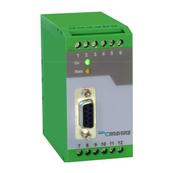
2. Introduction ZU 252 represents a small and low-cost, but highly performing converter for industrial applications, where incremental counting of positions or events must be converted to either analogue format or serial data. The unit has been designed as a compact module with 12 screw terminals and a 9-position SUB-D connector (female). -
Page 6: Applicable Encoders And Sensors
3. Applicable Encoders and Sensors The converter can accept the following impulse sources: The ZU252 converter can accept the following impulse sources: Quadrature encoders with HTL level output (10 – 30 V) and either PNP or NPN or Push- Pull or NAMUR characteristics, using A and B outputs wit 90°... -
Page 7: Terminal Assignment
4. Terminal Assignment We recommend connecting the Minus wire of the power supply to earth potential. Please observe that, under poor earthing and grounding conditions, multiple earth connections of screens and GND terminals may cause severe problems. In such cases it may be better to have only one central earthing point for the whole system. -
Page 8: Incremental Encoder Htl / 12-30V
4.2. Incremental encoder HTL / 12-30V The encoder may be supplied from the same source as the converter, or from another source. HTL encoder +24V ZU 252 converter Screen 12 (GND) 4.3. Proximity switches, photocells etc. This connection is fully similar to a HTL incremental encoder. With single-channel operation, input B remains unconnected or can be used to select the output polarity. -
Page 9: Serial Interfaces
4.6. Serial interfaces The unit provides a RS232 interface and a RS485 interface, however only one of the two can be used at a time. Serial communication allows to read out the counting result and to set parameters and variables by PC, according to need. GND int. -
Page 10: Dil Switch Settings
5. DIL Switch Settings There is one 8-position switch located on the top side (DIL1), and another 8-position switch is located on the bottom side of the unit (DIL2). These switches provide major settings of the desired properties of the unit. Changes of switch settings will become active only after cycling the power supply of the unit! Positions 7 and 8 of switch DIL2 are for internal factory use only and must... -
Page 11: Impulse Levels And Symmetric / Asymmetric Input Formats
5.2. Impulse levels and symmetric / asymmetric input formats Positions 5 and 7 of DIL1 together with positions 3 to 6 of DIL2 allow setting of all imaginable combinations of levels and formats. All subsequent tables use the following definitions: „0“... -
Page 12: Analogue Output Format
5.2.2. Settings for special applications Where you find that the standard settings shown before are not suitable for your application, please go through the following setting options and find out the input levels and characteristics you need. DIL1 DIL2 Characteristics of input A Characteristics of input B 5 6 7 3 4 5 6... -
Page 13: Selecting The Rs232 Or The Rs485 Serial Interface
5.4. Selecting the RS232 or the RS485 serial interface Position 1 of switch DIL1 selects between the RS232 interface and the RS485 interface. All connection details have already been explained in section 4.6. DIL1 / 1 Serial Interface RS232 interface is active (RS485 is switched off) RS485 interface is active (RS232 is switched off) 5.5. -
Page 14: Setup Procedure
6. Setup Procedure For all basic applications you can use the Teach feature for commissioning of the unit. Extended functions need a PC for setup and are described under section 8. As a first step it is advisable to check the input pulses by means of the LED marked “Status”. Position 6 of DIL1 must be set to ON for this test. -
Page 15: Operation As Single Channel Counter (Without Direction Signal) Or As Positional Counter (With Direction Signal)
6.1. Operation as single channel counter (without direction signal) or as positional counter (with direction signal) Settings: Make sure that the DIL switches are set according to the encoder in use, and that position 6 of switch DIL1 is OFF (Teach function active). ... -
Page 16: Readout Of The Actual Counter State By Serial Communication
7. Readout of the Actual Counter State by Serial Communication At any time you can read out the actual counter state and more values via serial link. For setting of serial communication parameters etc., you must however apply PC setup anyway, as shown later. -
Page 17: Pc Setup Using The Os3.2 Operator Software
8. PC Setup Using the OS3.2 Operator Software You can apply the full set of functions when you use a PC and our operator software OS3.x for setup of the unit (actual software version is OS3.2). You can download this software and more instructions from our homepage www.motrona.com Connect your PC to the converter, using a serial RS232 cable like shown in section 4.6 of this manual. -
Page 18: Displays And Softkeys
9. Displays and Softkeys The edit window for all unit parameters can be found on the left side of the screen. The INPUTS field shows the softkeys to switch the control commands on or off. Display boxes in the RS column indicate when the corresponding command is set to ON by PC. Display boxes in the PI/O column indicate that the corresponding command is ON by external hardware. -
Page 19: Parameter Settings
10. Parameter Settings Parameter Description „Register :8“ Setting: Multiplier These operands allow to convert the result to the desired engineering Divisor units. Offset The conversion affects the numeric value for serial read out from register <:8> only, but not the scaling of the analogue output. With the settings Multiplier = 1,0000... - Page 20 Parameter Description Edge Mode: This setting, with use of quadrature A/B input, allows simple count (x1) or full quadrature count (x4), by either accepting rising edges from input A only, or all rising and falling edges from inputs A and B simple count (x1) quadrature count (x4) Input Filter...
- Page 21 Parameter Description Analogue Setting Teach Minimum These settings define your minimum and maximum count for input A Teach Maximum (respectively A/B quadrature), where your analogue output moves from 0 V to 10 V. You can enter your minimum and maximum settings as follows: ...
- Page 22 Parameter Description Serial Communication: Unit Number: Especially with RS 485 applications it is necessary to attach a specific address to each unit, since up to 32 units can be connected to the same bus. You can choose any address number between 11 and 99. Factory setting = 11 The address must not contain a “0“...
- Page 23 Parameter Description Serial Timer: This register determines the cycle time in seconds for the cyclic transmission. E. g. with a setting of 0.100 the selected register value will be transmitted every 100 ms. The accuracy of the timer is +/-500 µs. Setting the register to 0 disables cyclic transmissions.
- Page 24 Parameter Description Backup Setting: Backup A Upon power-down the unit saves the actual counter values to the registers Backup Rest A Backup A and Backup B. Backup B Since the counters use impulse scaling factors, there may be remainders Backup Rest B which need to be considered later for error-free continuation of the count.
-
Page 25: Free Programmable Linearization
11. Free Programmable Linearization This programmable feature allows the user to convert the linear counting process to a non- linear analogue output. There are 16 programmable interpolation points available, which can be set in any desired distance over the full conversion range. Between two coordinates, the unit uses linear interpolation. - Page 26 You can visualize your curve on the PC screen or by means of an external oscilloscope. For this, select TOOLS, then TEST and there „Analogue Voltage Function“. The unit will now simulate a repeating counting cycle over the full range and generate the analogue signal accordingly.
-
Page 27: Monitor Functions
12. Monitor Functions The monitor function of the OS3.2 PC software allows to display some important data on the PC screen with a continuous refresh cycle. Select „Monitor“ from the „Tools“ menu to open the basic view of the monitor window. Click to “Define”... - Page 28 Click to the Status field, next to the desired register code (where you read ON or OFF). Now you can toggle this position between ON and OFF by touching any key. Set all of the register codes to ON which you afterwards would like to trace on the monitor. Switch all unused register codes to OFF.
-
Page 29: Data Readout Via Serial Interface
13. Data Readout via Serial Interface All register codes from chapter 12. are also available for serial readout by PC or PLC. For communication the FU252 converter uses the Drivecom Protocol according to ISO 1745. All protocol details can be found in our manual SERPRO_2a.doc which is available for download from our homepage www.motrona.com To request for a data transmission you must send the following request string to the converter:... -
Page 30: Test Functions
14. Test Functions When you select TEST from the TOOLS menu, you are able to verify the following data, by clicking to the corresponding field: Actual counter values DIL switch settings Internal supply voltages Analogue output state ZU25201c_e.doc / Jan-12 Page 30 / 34... -
Page 31: Dimensions
15. Dimensions 91mm (3.583’’) 40 mm (1.575’’) 74 mm (2.913’’) Side view Top view Front view ZU25201c_e.doc / Jan-12 Page 31 / 34... -
Page 32: Technical Specifications
16. Technical Specifications Power Supply : 18...30 VDC Power consumption : approx. 85 mA at 18 V approx. 60 mA at 30 V (+5.5V uncharged) Encoder supply : +5.5V +/- 5% (max. load: 250mA) Inputs (RS422/TTL differential) : RS422 compatible (differential level min. 1 V) or TTL differential, f = 1 MHz Inputs TTL single-ended... -
Page 33: Parameter List
Parameter List Parameter Default Positions Sign Ser. Code Multiplier -99999 99999 10000 +/- 5 Divisor 99999 10000 Offset -100000000 100000000 +/- 9 Direction AB Mode Linearisation Mode Edge Mode Input Filter Power-up Mode Factor A 99999 10000 Round Loop A 100000000 Set Value A -100000000 100000000... -
Page 34: Setup Form
17. Setup Form Date: Software: Operator: Serial No.: Register Setting (:8) Multiplier: Divisor: Offset: General Setting Direction: AB Mode: Linearization Mode: Edge Mode: Input Filter: Power-up Mode: Input Channel A Channel B Factor Round Loop Set Value Multiplier Analogue Setting Teach Minimum: Analogue Mode: Teach Maximum:...
Need help?
Do you have a question about the motrona ZU 252 and is the answer not in the manual?
Questions and answers