
Related Manuals for QSC Q-SYS QIO Series


Summary of Contents for QSC Q-SYS QIO Series
- Page 1 ® ™ Hardware User Manual QIO Series Network Audio I/O Expanders: QIO-ML4i, QIO-L4o, QIO-ML2x2 QIO Series Network Control I/O Expanders: QIO-GP8x8, QIO-S4, QIO-IR1x4 TD-001667-01-D *TD-001667-01*...
- Page 2 EXPLANATION OF TERMS AND SYMBOLS The term “WARNING” indicates instructions regarding personal safety. Failure to follow them may result in bodily injury or death. The term “CAUTION” indicates instructions regarding possible damage to physical equipment. Failure to follow them may result in equipment damage to equipment that may not be covered under the warranty.
-
Page 3: Maintenance And Repair
QSC authorized service station or an authorized QSC International Distributor. QSC is not responsible for any injury, harm or related damages arising from any failure of the customer, owner or user of the apparatus to facilitate those repairs. -
Page 4: What's In The Box
What’s in the Box QIO-ML4i (1x) (4x) (2x) QIO-ML4i Mic/Line In connector Power connector (orange) (black) (2x) (4x) (4x) Surface mounting Foam spacer M4 x 6 mm pan head bracket screws (1x) (1x) Warranty Safety and statement regulatory statements QIO-L4o (1x) (4x) (2x) - Page 5 QIO-ML2x2 (1x) (2x) (2x) QIO-ML2x2 Mic/Line In connector Line Out connector (orange) (green) (2x) (2x) (4x) Power connector Surface mounting Foam spacer (black) bracket (4x) (1x) (1x) M4 x 6 mm pan head Warranty Safety and screws statement regulatory statements QIO-GP8x8 (1x) (2x)
- Page 6 QIO-S4 (1x) (4x) (2x) QIO-S4 Serial connector Power connector (black) (black) (2x) (4x) (4x) Surface mounting Foam spacer M4 x 6 mm pan head bracket screws (1x) (1x) Warranty Safety and statement regulatory statements QIO-IR1x4 (1x) (1x) (1x) QIO-IR1x4 IR Output connector IR Input connector (black) (black)
- Page 7 Introduction The Q-SYS QIO Series offers multiple products that can serve numerous audio and control purposes. QIO-ML4i The Q-SYS ML4i is a network audio endpoint native to the Q-SYS Ecosystem, serving as a mic/line input that enables network-based audio distribution. The compact form factor includes surface mounting hardware permitting discreet and strategic mounting while an optional rack kit fits one to four devices into a standard 1U nineteen-inch format.
-
Page 8: Power Requirements
Power Requirements The Q-SYS QIO Series offers a flexible power solution that allows the integrator to choose to use either a 24 VDC power supply or an 802.3af Type 1 PoE PSE. With either power solution, you must follow the safety instructions for the specific power supply or injector chosen. - Page 9 Connections and Callouts QIO-ML4i Front Panel 1. Power LED – Illuminates blue when the Q-SYS QIO-ML4i is powered on. 2. ID LED – LED blinks green when placed into ID Mode via ID Button or Q-SYS Configurator. 3. ID Button – Locates the QIO-ML4i in Q-SYS Designer Software and Q-SYS Configurator. QIO-ML4i Rear Panel 1.
- Page 10 QIO-L4o Front Panel 1. Power LED – Illuminates blue when the Q-SYS QIO-L4o is powered on. 2. ID LED – LED blinks green when placed into ID Mode via ID Button or Q-SYS Configurator. 3. ID Button – Locates the QIO-L4o in Q-SYS Designer Software and Q-SYS Configurator. QIO-L4o Rear Panel 1.
- Page 11 QIO-ML2x2 Front Panel 1. Power LED – Illuminates blue when the Q-SYS QIO-ML2x2 is powered on. 2. ID LED – LED blinks green when placed into ID Mode via ID Button or Q-SYS Configurator. 3. ID Button – Locates the QIO-ML2x2 in Q-SYS Designer Software and Q-SYS Configurator. QIO-ML2x2 Rear Panel 1.
- Page 12 QIO-GP8x8 Front Panel 1. Power LED – Illuminates blue when the Q-SYS QIO-GP8x8 is powered on. 2. ID LED – LED blinks green when placed into ID Mode via ID Button or Q-SYS Configurator. 3. ID Button – Locates the QIO-GP8x8 in Q-SYS Designer Software and Q-SYS Configurator. QIO-GP8x8 Rear Panel 1.
- Page 13 QIO-S4 Front Panel 1. Power LED – Illuminates blue when the Q-SYS QIO-S4 is powered on. 2. ID LED – LED blinks green when placed into ID Mode via ID Button or Q-SYS Configurator. 3. ID Button – Locates the QIO-S4 in Q-SYS Designer Software and Q-SYS Configurator. QIO-S4 Rear Panel 1.
- Page 14 QIO-S4 Serial Port Pinouts The QIO-S4 features four serial ports: • COM 1 is configurable in Q-SYS Designer Software for RS232, RS485 Half Duplex TX, RS485 Half Duplex RX, or RS485/422 Full Duplex. • COM 2-4 ports are dedicated to RS232 communication. RS232 Pinout: COM 1 (Configurable), COM 2-4 (Dedicated) Signal Flow Description...
- Page 15 QIO-IR1x4 Front Panel 1. Power LED – Illuminates blue when the Q-SYS QIO-IR1x4 is powered on. 2. ID LED – LED blinks green when placed into ID Mode via ID Button or Q-SYS Configurator. 3. ID Button – Locates the QIO-IR1x4 in Q-SYS Designer Software and Q-SYS Configurator. QIO-IR1x4 Rear Panel 1.
- Page 16 QIO-IR1x4 IR Port Pinouts The QIO-IR1x4 features four IR outputs and one IR input: • Outputs 1-4 are configurable in Q-SYS Designer Software for IR or Serial RS232 mode. • Input provides 3.3VDC and receives IR data. IR Output 1-4: IR Mode Pinout Signal Flow Description Output...
-
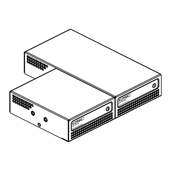
Page 17: Rack Mount Installation
Rack Mount Installation Q-SYS QIO Endpoints are designed to be mounted in a standard rack-mount unit using the Q-SYS 1RU rack tray (FG-901528-00). The rack tray accommodates up to four QIO Endpoint units of either product length. Rack Tray Hardware (1x) (3x) (14x) -
Page 18: Surface Mount Installation
Surface Mount Installation The QIO Endpoints can also be mounted under a table, on top of a table, or on a wall. For any of these mounting applications, use the surface mounting bracket and pan head screws included with the QIO Endpoint ship kit. The brackets are symmetrical to accommodate mounting right-side up to a ground-facing surface. -
Page 19: Warranty
© 2023 QSC, LLC. All rights reserved. QSC and the QSC logo, Q-SYS, and the Q-SYS logo are registered trademarks of QSC, LLC in the U.S. Patent and Trademark Office and other countries. Patents may apply or be pending. All other trademarks are the property of their respective owners.
Need help?
Do you have a question about the Q-SYS QIO Series and is the answer not in the manual?
Questions and answers