
Summary of Contents for AIR-TRANSFER N A Series
- Page 1 USER’S MANUAL N...A Air duct heater with an integrated temperature control module or a control unit...
-
Page 2: Table Of Contents
• After a careful reading of the manual, keep it for the entire service life of the unit. • While transferring the unit control, the user’s manual must be turned over to the receiving operator. www.air-transfer.nl... - Page 3 • Do not sit on the unit and avoid placing foreign objects on it. • Use the unit only for its intended purpose. THE PRODUCT MUST BE DISPOSED SEPARATELY AT THE END OF ITS SERVICE LIFE. DO NOT DISPOSE THE UNIT AS UNSORTED DOMESTIC WASTE. www.air-transfer.nl...
-
Page 4: Purpose
Designation example: Unit type Duct heater Connected air duct width [mm] 400, 500, 600, 700, 800, 900, 1000 Connected air duct height [mm] 200, 250, 300, 350, 400, 500 Heater power [kW] Phases 3 — three-phase Built-in control unit www.air-transfer.nl... -
Page 5: Technical Data
1 item x 1.2 N 250-2.0-1 A(Un) 1 item x 2.0 N 250-2.4-1 A(Un) 10.4 2 items x 1.2 N 315-1.2-1 A(Un) 1 item x 1.2 N 315-2.0-1 A(Un) 1 item x 2.0 N 315-2.4-1 A(Un) 10.4 2 items x 1.2 www.air-transfer.nl... - Page 6 15.2 10.5 3x3.5 N 500x250-12.0-3 A 17.4 12.0 3x4.0 N 500x250-15.0-3 A 1100 21.7 15.0 3x5.0 N 500x250-18.0-3 A 1320 26.0 18.0 3x6.0 N 500x250-21.0-3 A 1540 30.0 21.0 3x7.0 N 500x300-6.0-3 A 3x2.5 N 500x300-7.5-3 A 10.9 3x3.0 www.air-transfer.nl...
- Page 7 12x3.0 N 800x500-36.0-3 A 3960 78.0 54.0 18x3.0 N 800x500-54.0-3 A N 900x500-45.0-3 A 3300 65.0 45.0 15x3.0 N 900x500-54.0-3 A 3960 78.0 54.0 18x3.0 N 1000x500-45.0-3 A 3300 65.0 45.0 15x3.0 N 1000x500-54.0-3 A 3960 78.0 54.0 18x3.0 www.air-transfer.nl...
- Page 8 N 160-1.7-1 A(Un) N 160-2.0-1 A(Un) N 160-2.4-1 A(Un) N 200-1.2-1 A(Un) N 200-1.7-1 A(Un) N 200-2.0-1 A(Un) N 200-2.4-1 A(Un) N 250-1.2-1 A(Un) N 250-2.0-1 A(Un) N 250-2.4-1 A(Un) N 315-1.2-1 A(Un) N 315-2.0-1 A(Un) N 315-2.4-1 A(Un) www.air-transfer.nl...
- Page 9 N 160-5.1-3 A N 160-6.0-3 A N 200-3.4-1 A N 200-3.6-3 A N 200-5.1-3 A N 200-6.0-3 A N 250-3.0-1 A N 250-3.6-3 A N 250-6.0-3 A N 250-9.0-3 A N 315-3.6-3 A N 315-6.0-3 A N 315-9.0-3 A www.air-transfer.nl...
- Page 10 N 500x300-12.0-3 A 23.5 N 500x300-15.0-3 A 24.0 N 500x300-18.0-3 A 24.0 N 500x300-21.0-3 A 24.0 N 600x300-9.0-3 A 27.0 N 600x300-12.0-3 A 27.0 N 600x300-15.0-3 A 27.5 N 600x300-18.0-3 A 27.5 N 600x300-21.0-3 A 27.5 N 600x300-24.0-3 A 27.5 www.air-transfer.nl...
- Page 11 N 800x500-27.0-3 A 1024 20.6 1024 25.9 N 800x500-36.0-3 A 1024 36.1 N 800x500-54.0-3 A 1130 33.4 N 900x500-45.0-3 A 1130 38.0 N 900x500-54.0-3 A 1000 1020 1230 35.5 N 1000x500-45.0-3 A 1000 1020 1230 41.2 N 1000x500-54.0-3 A www.air-transfer.nl...
-
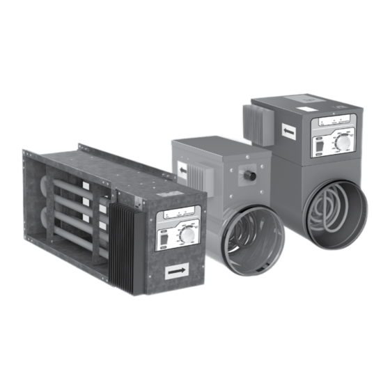
Page 12: Design And Operating Logic
The wiring diagram is given on the inside of the junction box lid. Junction box lid Heat sink Electric cable glands Temperature selection knob Remote temperature sensor (NK…Un series) Temperature sensor Casing Electric heating element www.air-transfer.nl... - Page 13 The N...A heaters with integral control units for rectangular ducts consist of a casing with a rigidly mounted junction box. The junction box has a removable front panel featuring the temperature control knob, the ON/OFF button and the indicator panel. Heat sink ON/OFF button Indicator panel Temperature control knob Casing Electric heating element Electric cable gland www.air-transfer.nl...
- Page 14 Internal controller 0–10 V Jumper 2 Temperature sensor feedback mode using three cascades Temperature sensor feedback 500 mA mode using cascade 1 Heating power output mainte- nance mode using cascade 1 Heating power output mainte- nance mode using three cascades www.air-transfer.nl...
-
Page 15: Mounting And Set-Up
The heater is designed for inline mounting in the air duct both horizontally and vertically. In a horizontal position the junction box must face upwards. The maximum deviation angle is 90°. The heater junction box may not face downwards. www.air-transfer.nl... -
Page 16: Connection To Power Mains
The supply voltage must be fed via an automatic circuit breaker with a minimum gap of 3 mm between the open contacts on all poles. The circuit breaker must be integrated into the stationary wiring in accordance with the applicable electrical wiring regulations. To access the terminal block remove the junction box (control unit) lid. www.air-transfer.nl... - Page 17 3x2.5 N 200-2.0-1 A(Un) 10.0 3x2.5 N 200-2.4-1 A(Un) 12.5 3x2.5 N 250-1.2-1 A(Un) 3x2.5 N 250-2.0-1 A(Un) 10.0 3x2.5 N 250-2.4-1 A(Un) 12.5 3x2.5 N 315-1.2-1 A(Un) 3x2.5 N 315-2.0-1 A(Un) 10.0 3x2.5 N 315-2.4-1 A(Un) 12.5 3x2.5 www.air-transfer.nl...
- Page 18 N 150-3.4-1 A N 160-5.1-3 A N 315-3.6-3 A N 160-3.4-1 A N 160-6.0-3 A N 315-6.0-3 A N 200-3.4-1 A N 200-3.6-3 A N 315-9.0-3 A N 250-3.0-1 A N 200-5.1-3 A N PE L1 L2 L3 N PE www.air-transfer.nl...
- Page 19 N 600x350-24.0-3 A N 700x400-18.0-3 A 31.5 N 700x400-27.0-3 A N 700x400-36.0-3 A 5x10 N 800x500-27.0-3 A 5x10 N 800x500-36.0-3 A 5x16 N 800x500-54.0-3 A N 900x500-45.0-3 A 5x10 N 900x500-54.0-3 A 5x16 N 1000x500-45.0-3 A 5x10 N 1000x500-54.0-3 A 5x16 www.air-transfer.nl...
-
Page 20: Control
The relays are connected to the controller circuit board via the TK 90 protective thermal contact at the factory. External wiring diagram External temperature Thermoresistor set point adjuster Air flow „Start” sensor signal 0–10 V controller Gnd Out E+ GND PTin PT+ GND 0-10В no Control Enable www.air-transfer.nl... -
Page 21: Technical Maintenance
The unit must be transported only in the working position. • Avoid sharp blows, scratches, or rough handling during loading and unloading. • Prior to the initial power-up after transportation at low temperatures, allow the unit to warm up at operating temperature for at least 3-4 hours. www.air-transfer.nl... -
Page 22: Manufacturer's Warranty
FOLLOWING THE REGULATIONS STIPULATED HEREIN WILL ENSURE A LONG AND TROUBLE-FREE OPERATION OF THE UNIT. USER’S WARRANTY CLAIMS SHALL BE SUBJECT TO REVIEW ONLY UPON PRESENTATION OF THE UNIT, THE PAYMENT DOCUMENT AND THE USER’S MANUAL WITH THE PURCHASE DATE STAMP. www.air-transfer.nl... -
Page 23: Certificate Of Acceptance
The unit has been installed in accordance with the provisions of all the applicable local and national construction, electrical and technical codes and standards. The unit operates normally as intended by the manufacturer. Signature: WARRANTY CARD Unit Type Нагреватель канальный Model NK________U_______ Serial Number Manufacture Date Purchase Date Warranty Period Seller Seller’s Stamp www.air-transfer.nl...
Need help?
Do you have a question about the N A Series and is the answer not in the manual?
Questions and answers