Advertisement
Quick Links
Thank you for your purchase of the Larson Electronics EXP-TSTAT explosion proof thermostat.
WARNING
TO AVOID THE RISK OF FIRE, EXPLOSION OR ELECTRIC SHOCK, THIS PRODUCT SHOULD BE INSTALLED,
INSPECTED AND MAINTAINED BY A QUALIFIED ELECTRICIAN ONLY, IN ACCORDANCE WITH ALL
APPLICABLE ELECTRICAL CODES.
TO AVOID ELECTRIC SHOCK:
•
BE CERTAIN ELECTRICAL POWER IS OFF BEFORE AND DURING INSTALLATION AND MAINTENANCE.
•
PRODUCT MUST BE CONNECTED TO A WIRING SYSTEM WITH AN EQUIPMENT-GROUNDING
CONDUCTOR.
TO AVOID EXPLOSION:
•
MAKE SURE THE SUPPLY VOLTAGE IS WITHIN THE VOLTAGE RATING.
•
ENSURE THE MARKED T RATING IS LESS THAN THE IGNITION TEMPERATURE OF THE HAZARDOUS
ATMOSPHERE.
•
DO NOT OPERATE IN AMBIENT TEMPERATURES ABOVE THOSE INDICATED ON THE PRODUCT
NAMEPLATE.
•
DO NOT OPERATE IF THE LENS, CORD, SEALS, HOUSING, RECEPTACLES, ETC. IS CRACKED OR
DAMAGED. IF SO, DISCONTINUE USE AND CONTACT MANUFACTURER FOR REPLACEMENT PARTS.
•
ALL FASTENERS SHOULD BE PROPERLY SEATED.
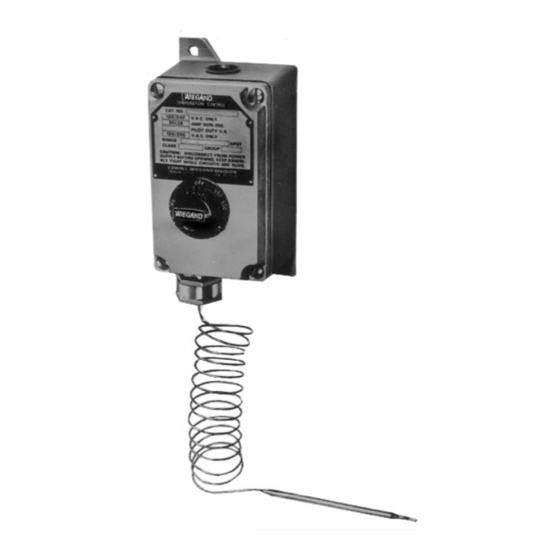
The Larson Electronics EXP-TSTAT-125.250-60.250F-0.25-V1-15L Explosion Proof Thermostat is designed for
temperature applications in industrial facilities where flammable gases, vapors or dust are or may be present. This 30-amp
device operates on 120-250V AC and comes with an adjustable point knob system, which features a DPST switch. The unit
is equipped with a fifteen-foot cable.
NOTICE: Type EXP-TSTAT controls are designed for
temperature control service only. Because they do not fail safe,
they should not be used for temperature limiting duty.
WARNING: Users should install adequate back-up
controls and safety devices with their electric
heating equipment. Where the consequences of
failure may be severe, back-up controls are essen-
tial. Although the safety of the installation is the
responsibility of the user, Larson Electronics will
be glad to make equipment recommendations.
Principle of Operation — Control action of these thermostats is
provided through the principle of liquid volume change. With a
variation in temperature, the liquid in the sensing bulb expands or
contracts, causing a bellows to actuate the switching mechanism.
Housing — The control housing and cover assembly is of heavy-
duty cast aluminum.
Control Range — The following temperature ranges are available:
0° to 100°
60° to 250°
Larson Electronics, LLC
Explosion Proof Thermostat
Instruction Manual
Fahrenheit
200° to 550°
300° to 700°
Phone: (877) 348-9680
EXP-TSTAT-125.250-60.250F-0.25-V1-15L
GENERAL
Process Temperature Differential — is variation in controlled
process temperature between maximum, when thermostat turns
OFF and minimum, when thermostat turns ON. This spread in
temperature may be minimized by —
1. Making sure control is mounted to vertical surface. (See Step
1, MOUNTING section.)
2. Avoiding excess heating capacity (oversized heaters).
3. Locating control sensing bulb in optimum position between
heat source and work.
In general, it is difficult to predict the actual operating dif-
ferential of a given process. Temperature differential may be as
low as 4°F for low range controls to as high as 17°F for high-
er range controls since the differential is a percentage function
of the dial range.
Packing Glands — If a sealed or leak-proof connection is required
at the point where the capillary enters the oven, tank, pipe or simi-
lar equipment, an appropriate packing gland is available as an
optional part.
Fax: (903) 498-3364
www.larsonelectronics.com
1 of 6
Advertisement

Summary of Contents for Larson Electronics EXP-TSTAT-125.250-60.250F-0.25-V1-15L
- Page 1 EXP-TSTAT-125.250-60.250F-0.25-V1-15L Explosion Proof Thermostat Instruction Manual Thank you for your purchase of the Larson Electronics EXP-TSTAT explosion proof thermostat. WARNING TO AVOID THE RISK OF FIRE, EXPLOSION OR ELECTRIC SHOCK, THIS PRODUCT SHOULD BE INSTALLED, INSPECTED AND MAINTAINED BY A QUALIFIED ELECTRICIAN ONLY, IN ACCORDANCE WITH ALL APPLICABLE ELECTRICAL CODES.
- Page 2 2 / " 2 / " 11 16 / " Calibration Cap White Nylon Universal Coupler Set Screw Lock Length (Refer to Specifications — Table A) Figure 1 Larson Electronics, LLC 2 of 6 Phone: (877) 348-9680 Fax: (903) 498-3364 www.larsonelectronics.com...
- Page 3 Figure 5 3. Set thermostat knob to OFF position and remove cover plate by loosening and removing four (4) fastening screws (see Figure 5). Larson Electronics, LLC 3 of 6 Phone: (877) 348-9680 Fax: (903) 498-3364 www.larsonelectronics.com...
- Page 4 Does Not Exceed Rating of Line Three Phase Control Thermostat Contactor and Single Voltage Phase when Load Exceeds Rating of Pilot Thermostat Light Load Figure 10 Figure 11 Larson Electronics, LLC 4 of 6 Phone: (877) 348-9680 Fax: (903) 498-3364 www.larsonelectronics.com...
- Page 5 Such changes voids U.L. listing of the control. Figure 15 Larson Electronics, LLC 5 of 6 Phone: (877) 348-9680 Fax: (903) 498-3364...
- Page 6 Larson Electronics. THESE INSTRUCTIONS MAY NOT COVER ALL DETAILS OR VARIATIONS OF THIS PRODUCT FOR YOUR EQUIPMENT OR INSTALLATION REQUIREMENTS. SHOULD FURTHER INFORMATION NOT COVERED BY THESE INSTRUCTIONS BE REQUIRED, PLEASE CONTACT LARSON ELECTRONICS BY EMAIL AT SALES@LARSONELECTRONICS.COM OR BY PHONE AT 1-877-348-9680 FOR FURTHER ASSISTANCE.