Table of Contents
Advertisement
Quick Links
Advertisement
Table of Contents

Summary of Contents for ASTLES SENSOLUTION C800
- Page 1 C800 Analyser Operating Manual Installation and Operating Instructions 902857-A - C800 Analyser Operating Manual.docx Astles Control Systems Ltd. B3 Regent Park, Summerleys Road, Princes Risborough, Bucks. HP27 9LE. Tel: +44 (0)1844 273301 sales@astles.co.uk http://www.astles.co.uk/...
-
Page 2: Table Of Contents
C800 Analyser Operating Manual Contents 1. Introduction ............................3 2. Mechanical Installation ........................4 2.1. Open Installation .......................... 4 2.2. Sighted Enclosure Installation ...................... 5 3. Electrical Installation ........................... 6 3.1. Power supply Requirements ......................6 3.2. 24V Supply Wiring ........................6 3.2.1. -
Page 3: Introduction
C800 Analyser Operating Manual 1. Introduction Thank you for selecting a C800 conductivity Analyser. The analyser converts an input from an electrochemical sensor to a 4-20mA signal for a PLC or chart recorder. The C800 is a microprocessor- based instrument that is designed to be sturdy and user-friendly. This analyser has many user-friendly features –... -
Page 4: Mechanical Installation
There is normally no need to bolt the flange down. 2.1. Open Installation If the analyser is to be mounted separately, use an Astles Control Systems universal mounting kit (500/9501) to fix it to a pipe or wall. To attach the analyser to the mounting kit use M6 bolts, washers, and nuts. -
Page 5: Sighted Enclosure Installation
C800 Analyser Operating Manual 2.2. Sighted Enclosure Installation To install the analyser into a sighted enclosure, the glands must be removed before passing the box through the window. Ensure the screen gasket is in place. Secure the analyser to the front of the enclosure using two screws either side of the analyser, shown below. -
Page 6: Electrical Installation
C800 Analyser Operating Manual 3. Electrical Installation 3.1. Power supply Requirements The C800 requires a 24V ±10% dc supply. Other devices such as chart recorders and PLCs may be connected in series. Use screened cable if the 4-20mA conductivity signal is required. 3.2. -
Page 7: Direct Connection To Analyser
C800 Analyser Operating Manual 3.2.3. Direct Connection to Analyser To wire directly to an external power source, wire +24V into the +ve terminal and 0V to the -ve terminal. Use 2-core screened cable, such as Belden 8760, through a gland in the bottom of the analyser. -
Page 8: Display And Keypad Functions
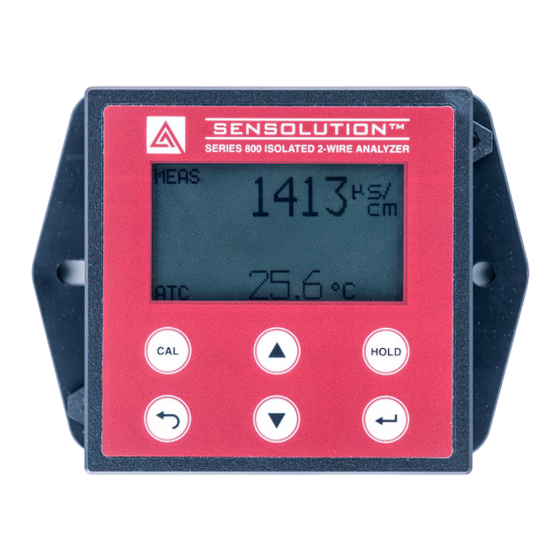
C800 Analyser Operating Manual 4. Display and Keypad Functions 4.1. Display 1. Measurement mode indicator 2. Measurement reading 3. Hold mode indicator 4. Automatic Temperature Compensator indicator 5. Temperature Reading 4.2. Keypad Description The C800 analyser has 6 buttons on the keypad allowing for easy and quick operation of the analyser. -
Page 9: Pin Code
C800 Analyser Operating Manual (Back): Navigates to the previous screen. Hold the button for 2 seconds to return to the primary display. (Down-Arrow): Allows you to scroll through various menus or decrease calibration values. (Enter): Will confirm selections in menus and calibration values. Pressing this button when on the primary display will navigate to the main menu. -
Page 10: Basic Setup
C800 Analyser Operating Manual 7. Basic Setup 7.1. Range Setup Navigate to the RANGE menu to set an appropriate conductivity range for the solution you are measuring. Navigate to the DSL-DSH menu to specify a custom range for the 4-20 mA current output. On an aluminium beverage can line, the typical ranges for stages 3 &... -
Page 11: Calibration
7. To perform calibration you will require conductivity standards. Standards are available in 84μS and 1413μS and can be purchased by emailing sales@astles.co.uk. When calibration has started the analyser will go into a temporary hold mode until the calibration is complete. -
Page 12: Temperature Calibration
C800 Analyser Operating Manual Press again to confirm the slope and the offset. The analyser will then ask if you would like to reset the runtime, select NO for this. The sensor is now calibrated. 8.2. Temperature Calibration By default ATC mode is enabled. Temperature calibration is only possible when an ATC probe is fitted. - Page 13 C800 Analyser Operating Manual If there is no ATC available, disable ATC mode and manually set the process temperature. Set the manual temperature to the desired value and press to confirm. The default value for manual temperature is 20.0 °C but it can be set between 0 –...
-
Page 14: Main Menu
C800 Analyser Operating Manual 9. Main Menu The main menu can be accessed by pressing the button and contains 13 different options. This section will give an explanation to those options. CALIBRATE – This takes you to the calibration screen. This has the same function as pressing the CAL button. - Page 15 C800 Analyser Operating Manual RANGE – Select the range appropriate for the process. Lower ranges give greater accuracy and higher ranges permit higher readings. DSL-DSH – This allows the user to set the low and high process values that correspond to 4 and 20mA respectively.
- Page 16 C800 Analyser Operating Manual HOLD – This allows the user to enable or disable hold mode. This has the same functionality as pressing the HOLD button. See section SYSTEM INFO – This displays system information for the analyser: • Conductance •...
- Page 17 902857-A - C800 Analyser Operating Manual.docx...
- Page 18 C800 Analyser Operating Manual 902857-A - C800 Analyser Operating Manual.docx...
- Page 20 Astles Control Systems Tel: +44 (0)1844 273301 B3 Regent Park, Summerleys Road, sales@astles.co.uk Princes Risborough, HP27 9LE. UK. http://www.astles.co.uk 902857-A - C800 Analyser Operating Manual.docx...
Need help?
Do you have a question about the SENSOLUTION C800 and is the answer not in the manual?
Questions and answers