
Related Manuals for Woodward DSS-2


Summary of Contents for Woodward DSS-2
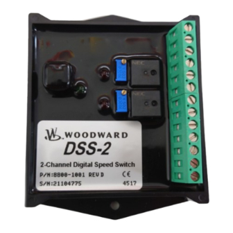
- Page 1 Application Note DSS-2 Two-Channel Digital Speed Switch Installation Guide Application Note 36599A...
- Page 2 Revisions—Text changes are indicated by a black line alongside the text. Woodward Governor Company reserves the right to update any portion of this publication at any time. Information provided by Woodward Governor Company is believed to be correct and reliable. However, no responsibility is assumed by Woodward Governor Company unless otherwise expressly undertaken.
- Page 3 Declaration of Conformity The official Declaration of Conformity is available upon request. Please see the “How to Contact Woodward” section in Chapter 7 to request a copy. It is also printed in User Manual 36598, which can be accessed online at www.woodward.com...
-
Page 4: Electrostatic Discharge Awareness
PCB from the control cabinet, place it in the antistatic protective bag. CAUTION To prevent damage to electronic components caused by improper handling, read and observe the precautions in Woodward manual 82715, Guide for Handling and Protection of Electronic Controls, Printed Circuit Boards, and Modules. Woodward... -
Page 5: Chapter 1. General Information
DSS-2 has two multi-turn potentiometers for speed setpoint adjustment. A serial interface is provided for additional adjustments with the All-purpose Calibration Tool (ACT). DSS-2 can be re-configured with the ACT to act as a glow plug controller or engine autocrank controller. Intended Usage The DSS-2 is intended as a sub-system for integration into construction/commercial and industrial engine systems by original equipment manufacturers and industrial plants. -
Page 6: Chapter 2. Installation
Application Note 36599A DSS-2 Two-Channel Digital Speed Switch Chapter 2. Installation CAUTION Take adequate protection to ensure personal and equipment safety and follow the suggested installation sequence given below. Refer to Figures 1 & 2 to install the system and subcomponents. - Page 7 Reset Switch Input (RST): A switch to battery positive switch input is provided for manual reset functions. DSS-2 is factory programmed for automatic reset at 80% of set speed, but may be modified with the ACT for manual or latched reset.
- Page 8 Application Note 36599A DSS-2 Two-Channel Digital Speed Switch Controller Pinout Use the diagram below to connect your DSS-2 controller to battery power, the mag pickup, loads, switches and ACT. NOTE All cabling for the DSS-2 controller is limited to less than 3m (9.84’).
-
Page 9: Chapter 3. Calibration
4. Adjust speed setpoints until desired set speeds are achieved. Red LEDs should illuminate when set speeds are reached. 5. Install DSS-2 on engine and confirm MPU input with engine running. Confirm speed switch operation. If concerned about overspeeding the engine or load, attach 12 volts to the verify (VER) input. -
Page 10: Chapter 4. Diagnostics
The green status LED on the DSS-2 can be used for diagnosing a variety of problems: • When the DSS-2 is powered up, all three LEDs will turn on for one second then turn off. If they do not, the DSS-2 is either not receiving power or it is completely non-functional. •... - Page 11 Application Note 36599A DSS-2 Two-Channel Digital Speed Switch Woodward...
- Page 12 Phone +1 (970) 482-5811 • Fax +1 (970) 498-3058 Email and Website—www.woodward.com Woodward has company-owned plants, subsidiaries, and branches, as well as authorized distributors and other authorized service and sales facilities throughout the world. Complete address / phone / fax / email information for all locations is available on our website.
Need help?
Do you have a question about the DSS-2 and is the answer not in the manual?
Questions and answers