Table of Contents
Advertisement
Quick Links
Advertisement
Table of Contents

Summary of Contents for MIKAFON DOC16
- Page 1 DOC16 Main Control Unit USER MANUAL...
-
Page 2: Table Of Contents
Table of Contents 2. DOC16 MAIN CONTROL UNIT ......................... 6 2. a. Device Characteristics ........................6 2. b. Device Functions & Specifications ....................7 3. CONTROLS, CONNECTORS & INDICATORS ..................... 8 3.1. Front Panel ............................8 3.1.1 LCD Touchscreen ........................9 1. - Page 3 5.b. Others ........................... 34 5. DSP SETUP ............................35 5.1. Introduction & Connection ......................35 5.2. Menus & Instructions ........................35 5.2.1. DOC16 Output Menu ......................35 a. Naming............................36 b. Gain ............................36 c. Equalizer............................ 37 d. Crossover ..........................37 e.
- Page 4 IMPORTANT NOTICES • Before installing and using the device, please read this manual carefully and keep it for further use. • This manual is an integral part of the product. It should be given to the new owner in order for them to know the installation, operation and safety instructions.
- Page 5 PRECAUTIONS • Do not cover ventilation of the product. • Do not allow amplifier to operate with an excessive load for a long time. • Tighten the screws on the speakers firmly to guarantee safe contact. • Do not use thinner, alcohol or other volatile substances when cleaning exterior parts.
-
Page 6: Doc16 Main Control Unit
DOC16 is the main control unit of the system with 16 channels. The DOC16 is an Ethernet based PA/VA system, which supports up to 16 channels. Designed to operate decentralised, it’s not only fully reliable, it also provides the highest safety functions such as spare power amplifier switching, failure detection and indication in all emergency tasks, real time speaker line impedance monitoring and reliable open circuit or short-circuit detection. -
Page 7: Device Functions & Specifications
18. System is expandable up to 64 zones. 19. Lets any fault description to be seen from the LCD touch screen. 20. Traceable and recordable logs are held within the system. 21. Supports announces and messages to be kept in memory and broadcasted according to given priority, except emergency situations. -
Page 8: Controls, Connectors & Indicators
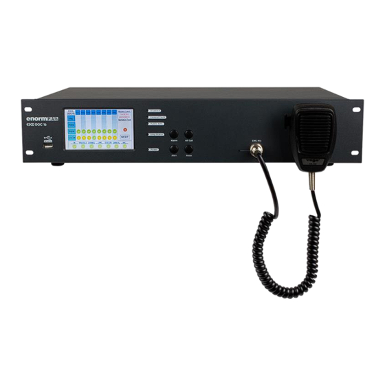
3. CONTROLS, CONNECTORS & INDICATORS 3.1. Front Panel Figure 1 DOC16 Front Panel 1. Media: USB (mp3) input used for broadcasting music to the system. 2. Disabled LED: Lights up yellow when the respective function (“Disable”) is selected from the interface. In this case, tests in order to find faults according to EN54-16 will not be performed, all will be disabled. -
Page 9: Lcd Touchscreen
12. LCD Screen: 5” LCD touchscreen. Detailed information is given in the following. 3.1.1 LCD Touchscreen From the 5” LCD Touchscreen in front of DOC16, various controls can be made and statuses can be monitored. When DOC16 is energized the default page on LCD Touchscreen is “Amplifier Status”. -
Page 10: Amplifier Status
1.a Amplifier Status i. Monitoring Page Zones that are connected to amplifiers can be monitored through this page. It is the default page of LCD Touchscreen. In order to access the main menu, cross sign is pressed and password is entered. Once the password is entered user can see that she is in Access Level 2 from top right. - Page 11 10. SYSTEM: Monitors the status of processor (CPU) in DOC16. If there’s no problem a green check, otherwise a yellow exclamation point will be seen on the screen.
-
Page 12: Password
15. ACCESS LEVEL: It can be seen at which access level the interface is (Figure 4). To enter Access level 2, it requires a password. Please see the part below. (ii. Password) Operations other than Amplifier Status monitoring, require password and accepted as access level 2. -
Page 13: Zone Selection
iii. Zone Selection Figure 6 LCD Touchscreen / Zone Selection Above screen (Figure 6) is the zone selection screen which pops up after the password screen (see Figure 5) when an operator presses Alarm or Alert buttons or Emg microphone latch in order to make an announcement. -
Page 14: Amplifier Errors
1. Main Power Supply Error: Indicates which amplifier has a problem with mains (220VAC). 2. Battery Power Supply Error: Indicates which amplifier has a problem with batteries (48VDC). 3. Canbus Error: Indicates any interruption on the interface between DOC16 controller and the respective D4250IP amplifier. -
Page 15: Settings
1.b Settings Settings menu include 3 sub-menus. Please see detailed explanation below. In order to enter Settings menu, password is required. Once password is entered, the system operates at access level 2. After 180 seconds with no operation, system automatically returns to access level 1. To return to access level 1 manually, go back to “Amplifier Status”... -
Page 16: Calibrate
System is calibrated with this menu. It is recommended to calibrate the system in certain periods. iii. Line Control With line control menu, all the lines connected to the DOC16 is controlled for any short circuit or interruption. 1.c Emg This part is for future use. -
Page 17: Rear Panel
3.2. Rear Panel Figure 15 DOC16 Rear Panel 1. 220V AC 220W: Input of mains power. Mains must be grounded. 2. 24V DC 10A: Input of backup battery. If the system is desired to meet EN54-16 requirements, the input should be fed by a power supply with EN54-4 certificate. - Page 18 There are 16 static and 4 programmable business (B1, B2, B3, B4) dry contacts in DOC16. Any mp3 file can be uploaded to all contacts via the web interface. Also business contacts can be grouped by assigning different zones. If there is a problem with the cables at the contact ends which are connected to the activated inputs, CIE error will be seen in LCD screen.
- Page 19 *X and Y stands for any of the 16 contacts The signal coming out of AMP. SIG OUT’s “X” channel on DOC16, can be connected to D4250IP LINE IN 1, 2, 3 or 4 as desired. If the signal is entered to for example LINE IN “Y”, take an output from CH”Y”...
-
Page 20: Computer Setup
For connection to DOC16 via web interface, system asks for a user name and a password. By default the user name is “admin” and the password is “123456”. You can change the password from user operations menu later on. -
Page 21: Device Setup
Figure 21 General System Setup 1.a Device Setup Please see Figure 22. Allows user to configure below settings; ➢ System Name Setup: Name of the device is given from this section. ➢ Network Setup: IP configuration of the device is made from this section. After changing IP address, Submit button is clicked and device is restarted by clicking Reboot icon ( ➢... -
Page 22: File Manager
1.b File Manager Please see Figure 23. Allows user to configure the files that will be uploaded to device. Messages, Message Tones and Announcement Tones can be uploaded from this section. Audio files must be in mp3 format. Figure 23 General System Setup / File Manager ➢... - Page 23 ➢ Message Tone: Message jingles (sounds right before and after the message broadcasts) are selected from this section. Please see Figure 25. To upload a message tone audio file, the “Upload” button is clicked. The screen in Figure 24 will be seen. Select File is clicked and the file path is selected.
-
Page 24: Device Match
1.c Device Match Please see Figure 27. All the microphones/announcement consoles (MA5) that are connected to the system, are automatically detected and listed under this section. Microphones are listed by clicking “List” icon. Microphones that are going to be defined to the device can be selected manually by “Select All”... -
Page 25: Control Input
2. Control Input Allows operator to configure the inputs. When clicked, tab in Figure 29 is seen. It has three sub- menus; Input Contacts, Control Input and Control Buttons. Figure 29 Control Input 2.a Input Contacts Please see Figure 29. All the input contacts can be configured from this tab. To see and configure more inputs including EMG Inputs, scroll down the page. -
Page 26: Control Input Setup
2.b Control Input Setup Please see Figure 31. The messages which will be broadcasted to that particular zones (contacts) are selected from this section. The configuration is seperated for contacts 1 to 16 by Control 1…16 and for business contacts (EMG Inputs) B1, B2, B3 and B4. Configuration of Control 1…16: Figure 31 Control Input Setup for Contacts 1 to 16 ➢... - Page 27 Configuration for B1, B2, B3, B4: EMG Input 1, 2, 3 and 4 are called business contacts and represented as B1, B2, B3 and B4 respectively. An example will be shown for B1, the rest of the contacts have the same configuration.
-
Page 28: Control Buttons
➢ Contact Out(s): Contacts that are going to be activated when B1 emergency contact become active, are selected from this section. Figure 34 Control Input Setup / Contact Output(s) ➢ Priority: Priority is selected between B1, B2, B3 and B4. Figure 35 Control Input Setup / Priority Ranking 2.c Control Buttons Please see Figure 36. -
Page 29: Audio
3. Audio Allows operator to do configure mainly audio settings of the zones. When clicked, this tab is seen as Figure 37. It has three subtitles; Zone Names, Speaker Out Setup and Audio Matrix. Figure 37 Audio 3.a Zone Names Please see Figure 37. -
Page 30: Speaker Out Setup
After the changes, “Submit” button is clicked. 3.c Audio Matrix Figure 40 Audio / Audio Matrix ➢ Audio Matrix Setup: Configuration of MS40 (music server) is made from this section. Directions can be accessed from MS40 User Manual ( www.mikafon.com.tr... -
Page 31: Scheduled Tasks
4. Scheduled Tasks Allows operator to schedule detailed announcement tasks to the system. Please see Figure 41. Figure 41 Scheduled Tasks Setup In the tasks list, the name given to the task, the repetition count and the message that is going to be announced can be seen. - Page 32 ➢ Name: Name of the task is defined. ➢ Start Date: Starting date of the task is determined. NOTE: Dates are accepted in day/month/year format! ➢ Stop On: Termination date of the task is determined. Activate the button by clicking on it to enter a date.
-
Page 33: Other System Setup
5. Other System Setup Allows operator to; identify the elements in the system, also do operations like speaker line control and rebooting. Please see Figure 46. Figure 46 Other System Setup / Amplifier Connection 5.a. Amplifier Connection Please see Figure 46 and Figure 47. Device types are written as titles; Announcement, Music, Ann/Music and Spare. -
Page 34: Others
As indicated in part 3.2 (10), amplifier inputs to DOC16 has a certain designated configuration. See Table 4 below. Amplifier Input # Announcement Music 1 , 5, 9, 13 2, 6, 10, 14 3, 4, 7, 8, 11, 12, 15, 16 Table 4 DOC16 Input Amplifier Designation ➢... -
Page 35: Dsp Setup
DOC16 DSP interface consists of two different menus. One is “DOC16 Output” where the DSP effects can be controlled, the other one is “Settings” where varying operations can be done. 5.2.1. DOC16 Output Menu As seen in Figure 50 DSP settings like naming the outputs, muting, etc. can be done from DOC16 Output Menu. -
Page 36: Naming
Figure 50 DOC16 Output Menu a. Naming: Can be customized by giving different names to different outputs. It is recommended to choose a name that is indicating that zone. b. Gain: Gain of the inputs can be adjusted from this section. Any value can be given between - 20 to +20 dB. -
Page 37: Equalizer
c. Equalizer: Various improvments over the audio can be done from this section. Please see detailed information from 5.2.2.a.Equalizer (pg.39). Figure 52 Output Settings / Equalizer d. Crossover: The regions that are above or below the cutoff frequency of the audio signals can be blocked by Crossover. -
Page 38: Limiter
e. Limiter: High abrupt points in the audio signal can be limited to a certain threshold, clipped, etc. Please see detailed information from 5.2.2.c. Limiter (pg. 41). Figure 54 Output Settings / Limiter f. Volume: Output audio level can be adjusted. Any value between 0 – 40 dB can be given Please see Figure 55. -
Page 39: Invert
g. Invert: Signal can be inverted separately at the right and left channels Please see Figure 56. Figure 56 Output Settings / Line Input 1 Inverter h. Channel X: Any desired channel can be muted by clicking on the corresponding box. 5.2.2. -
Page 40: Crossover
1. Parametric Equalizer: Consists of 7 filters. Specifications of any of the filter can be changed manually from the graph or from the table below, over Frequency. 2. Flat: Values of all filters can be reset to “0” by clicking on this button. 3. -
Page 41: Limiter
8. Filter Type: The desired filter can be chosen from existing filter options. Options are: Butterworth 24, Butterworth 12, Bessel 12, Bessel 24. 9. Enable/Disable: Crossover can be disabled and enabled again from this button. 5.2.2.c. Limiter This section is reserved only for Limiter description. Figure 59 Output Settings / Limiter 10. -
Page 42: Settings Menu
13. Update Address File: Button used for updating the address file path. 14. DOC-16 Device Update: The "DOC16 Device Update" button on the top right allows the changes made to be saved. Thus, even if the device is turned off and on again, the settings made will remain saved. -
Page 43: Installation & Commissioning Instructions
6. INSTALLATION & COMMISSIONING INSTRUCTIONS The controller unit DOC16 is suitable for either table-top or 19-inch rack installation. When placing the device, for it to be operated smoothly, the ventilation gaps should not be blocked on both sides of the case and the device should be screwed from the 4 corners to the rack cabinet. - Page 44 Controller and Announcement Console Connection Proceed as follows; 1. Connect DOC16 Ethernet port to at least a dummy switch with a CAT5 cable. 2. Connect MA5 Ethernet port to the same switch as DOC16 is connected. * Be sure that devices are not supplied with power.
-
Page 45: Technical Specifications
Rear Performance AC Power socket Main Amplifier: Frequency Integrated 48kHz 24V Backup input DOC16: 16 x 50V or 100V (each Response 24bits – 344 MIPS 1x Ethernet Interface 10M/100M – max 300W) >75dB WAN/LAN Spare Amplifier: Min./ Max. Load: 1x Fireman Out RS485 ... -
Page 46: Cable Connection Diagram
Figure 62 DOC16-D4250IP Connection Scheme Figure 62 shows mono connection between 1 DOC16 and 2 D4250IP. For mono connection, the 2P dip switch levers on the D4250IP rear panel should be in the upright position. For detailed information, refer to the D4250IP user manual: www.mikafon.com.tr... - Page 47 Example 2 Figure 63 DOC16-D4250IP Connection Scheme The figure above (Figure 63) shows the mono connection type between 1 DOC16 and 4 D4250IP and 1 redundant D4250IP. For mono connection details, refer to the D4250IP user manual.
- Page 48 Figure 64 DOC16-D4250IP Connection Scheme Figure 64 shows bridge connection between 1 DOC16 and 2 D4250IP. One amplifier is for announcement and the other is used for music. For bridge connection, the 2P dip switch levers on the D4250IP rear panel should be in the downright position. For detailed information, refer to the D4250IP user manual: www.mikafon.com.tr...
- Page 49 Example 4 Figure 65 DOC16-D4250IP-DCR 30A Connection Scheme The figure above (Figure 65) shows the wiring diagram for EN54-16 installation between 1 DOC16 and 4 D4250IP, 1 redundant D4250IP and 1 DCR 30A.
-
Page 50: Block Diagram
9. BLOCK DIAGRAM... -
Page 52: Declaration Of Manufacturer
10. DECLARATION OF MANUFACTURER... -
Page 54: Comformity
11. COMFORMITY... -
Page 55: Warranty
WARRANTY 12. WARRANTY WARRANTY: 2 (TWO) YEARS VALIDITY MEAN TIME TO REPAIR: 30(THIRTY) WORK DAYS...
Need help?
Do you have a question about the DOC16 and is the answer not in the manual?
Questions and answers