Advertisement
Quick Links
Advertisement

Summary of Contents for FOCOMM SW-M-8G-2SFP
- Page 1 User manual SW-M-8G-2SFP 8 port Gigabit Layer 2 Managed PoE Switch...
- Page 2 Installation manual introduction The Product installation manual mainly describes switch hardware features, installation methods, and precautions during the installation This manual includes the following chapters: Chapter 1: Product Introduction. Briefly describes the basic features, Detailed hardware & software specifications of the switch and the appearance details.
-
Page 3: Chapter 1: Product Introduction
Chapter 1: Product Introduction 1.1 Products description SW-M-8G-2SFP is managed PoE switch for security transmission and WIFI coverage, meet the need of PoE power supply for WIFI AP, IP-camera, WIFI bridge, IP phones and other types of equipment. New generation of... - Page 4 1.2 Product Features Full Gigabit Port 8 1000Mbps RJ45 ports (support PoE power supply) with 2 Gigabit SFP ports, Data transmission is not jammed. Realtek chip, the performance is more stable and powerful Realtek high-performance chip can greatly improve network data processing rate Convenient operation AI VLAN mode: Separating 1-8 ports from each other, can effectively...
- Page 5 1.3 product specification Hardware Specifications Chipset RealtekHigh Performance Chipset Flash 16MB 128DDR Port 8 10/100/1000Mbps RJ45 ports 2 Gigabit SFP fiber ports 8 10/100/1000Mbps RJ45 port support Max 96W Single port max 46W 10 Link/Act LEDs 8 POE LEDs LEDs 1 Power LEDs 1 SYS LED Forwarding mode: store and forward...
- Page 6 Software Specifications IEEE 802.3: Ethernet Media Access Control (MAC) protocol IEEE 802.3i:10BASE-T Ethernet IEEE 802.3u:100BASE-TX fast Ethernet IEEE 802.3ab:1000BASE-T gigabit Ethernet IEEE 802.3z:1000BASE-X gigabit Ethernet (fiber) IEEE 802.3ad: comply link aggregation standard Network standard IEEE 802.3x: flow control IEEE 802.1p: About the traffic priority of the second layer of Qos / Cos protocol (multicast filtering) IEEE 802.1q:VLAN Bridge operation...
- Page 7 DHCP Support DHCP Snooping Support 4K VLAN VLAN Support 802.1Q VLAN、Port VLAN、Voice VLAN Comply the IEEE 802.1d standard Support MAC address learning and aging MAC address table automatically Support static, dynamic, filter address table Password protection Support based on the port number, IP address, MAC address restrictions on user access Support HTTPS、SSL V3、TLS V1、SSH...
- Page 8 Support 802.1X AAA Support port security, port isolation Support CPU protection Support setting the PoE port priority Support viewing POE Chip Status Support setting PoE power supply period Support setting port power Support L2(Layer 2)~L4(Layer 4) packet filtering function Access control (ACL) Support port mirroring, port redirection, flow rate limit, QoS re-marking Support 8 port queue...
- Page 9 Support multicast VLAN Support STP(IEEE 802.1d),RSTP(IEEE 802.1w) and MSTP(IEEE 802.1s) protocol Spanning Tree Support loop protection, BPDU protection, TCprotection,BPDUfilter Support for multicast suppression Support broadcast suppression Storm suppression Support for unknown unicast suppression Support static aggregation Support dynamic aggregation Link aggregation Support IP, MAC, hybrid load balancing mode Supports up to 32 aggregation groups...
- Page 10 Support SNMP V1/V2/V3 Support LLDP、RMON SNMP Support Support ARP Protection, IP Source protection、DoS protection Support Apollo Cloud Platform Support CPU monitor、memory monitoring Support system log Support Ping, Tracert detect cable testing...
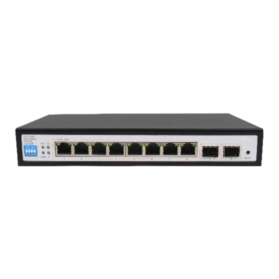
- Page 11 1.4 Appearance Front Panel Including indicators, RJ45 port, DIP switch, RST button, SFP port, as shown below indicator SW-M-8G-2SFP The indicator working status is shown as the following table Indicators Title Description statu Solid Power is normal No power, the power...
- Page 12 The corresponding RJ45 port is connected to the Solid powered device and the power supply is normal POE power Yell The corresponding RJ45 indicator port is not connected to the powered device or the power supply is abnormal Blink A valid link is Connection established LINK/ACT...
- Page 13 When the switch mode of operation is CCTV mode, 1-8 port can support 250 meters power supply with 10Mbps speed rate SFP Port SW-M-8G-2SFP provides 2 Gigabit SFP optical ports (SFP1, SFP2), can be inserted into the Gigabit SFP module...
- Page 14 RST Button When the switch is powered on, press the button with the needle to release the device and enter the restarting state. When the SYS lamp restarts, the device restarts. When the switch is powered on, press and hold the button for more than 5s to release the button and enter the reset state.
- Page 15 product lightning strikes and extend product life Chapter2 Installation 2.1 Installation Precautions Note:To avoid improper use of equipment damage and personal injury, please observe the following precautions Installation safety precautions The power should be kept off during the installation, while wearing ...
- Page 16 do not wipe it with wet cloth. Do not wash it with liquid temperature and humidity To ensure the long-term stability working of the switch, please maintain a certain temperature and humidity environment. High or low humidity easily lead to leakage of insulation materials, deformation and even the corrosion of metal parts, the temperature is too high will accelerate the aging process of insulating materials, seriously affecting the service life of equipment.
- Page 17 some measures in anti-static, but when the static electricity exceeds a certain intensity, it will still cause fatal damage to the electronic components on the internal circuit board. In order to prevent static electricity from affecting the normal operation of the equipment, please note the following: 1.
- Page 18 lightning protection, please note the following: 1. Make sure the rack and the ground to maintain good contact; 2. Make sure the power outlet is in good contact with the earth; 3. Reasonable wiring, to avoid the internal sense ray; 4.
-
Page 19: Chapter3 Hardware Connection
Chapter3 Hardware connection 3.1 RJ45 port connection Connect the RJ45 port of the switch and the corresponding network device via cables, the POE power supply function of the switch is default enabled on the downlink port of the switch, which can be used for IEEE802.3af or IEEE802.3at standards powered devices such as APs, bridges, and network cameras Note:... - Page 20 Do not connect the RJ45 port to the phone line SFP Port connection SFP port only support Gigabit fiber module. Recommended use of standard SFP module products The process of installing a fiber module on a switch is as follows: 1、grasp the optic fiber module from the side, insert it smoothly along the SFP port slot until the optic fiber module and switch are in close contact;...
- Page 21 eyes as this may cause eye injury Check before power on Check whether the outlet power supply meets the switch specifications; Check the power, switches, racks and other equipment have been properly grounded; Check whether the switch and other network devices are connected properly Device initialization The switch automatically initializes when the power switch is turned on.
- Page 22 Step2、 Manually changed the computer IP address to 192.168.254.X (X is 2 ~ 254), subnet mask is 255.255.255.0 Step3、Open computer's browser, type 192.168.254.1 in the address box, hit the Enter key Step4、Enter the default username and password “admin” and then click Login...
- Page 23 Step5、 Entered the switch web management interface successfully when you see picture as below, you can begin to configure the switch...
- Page 24 Chapter 4: Packaging and product usage suggestions 4.1 Open the package carefully check the following list Commodity Quantity Description PoE switch 1pcs Power cord 1pcs Optional Bracket 2pcs Fixed on rack mount After-sale 1pcs Used for after-ale service card service User manual 1pcs Guide users to install...
- Page 25 6. When the product is powered on, please do not plug or unplug the cable except for special circumstances. 7. Do not use the switch in places with excessive dust and electromagnetic radiation. Do not use the switch in a place with high temperature and no ventilation;...
Need help?
Do you have a question about the SW-M-8G-2SFP and is the answer not in the manual?
Questions and answers