Table of Contents
Advertisement
Quick Links
Advertisement
Table of Contents

Summary of Contents for SMAR SR301
- Page 3 Introduction INTRODUCTION The SR301 is a Remote Seal that allows the pressure transmitter to make measures in situations where the immediate contact of the transmitter diaphragm with the process fluid it is not allowed. The remote seal is made up by one connection with the diaphragm and one capillary connection with filling fluid.
- Page 4 Thus, in choosing the seal size these factors must be considered according to each case to guarantee excellent performance and long-life span. This manual was made to help install, operate, and maintain the SR301. It contains information about transmitter/seal assembly, organized in the following categories: •...
- Page 5 Smar provides specific training to instruct and qualify such professionals. However, each country must comply with the local safety procedures,...
-
Page 6: Table Of Contents
Table of Contents TABLE OF CONTENTS CHAPTER 1 - INSTALLATION ..................... 1.1 APPLICATION ................................. 1.1 GENERAL RECOMMENDATIONS FOR REMOTE SEAL USE................1.1 TYPE OF REMOTE SEAL ............................1.2 RECEIVING AND HANDLING ..........................1.2 MOUNTING OF TRANSMITTER WITH REMOTE SEAL ..................1.2 CHAPTER 2 - SELECTION ...................... - Page 7 Introduction EXAMPLE 2 ................................5.9 ERROR CALCULATION BY TEMPERATURE ........................ 5.11 CALCULATION OF SEAL/LEVEL ERROR ........................5.11 CALCULATION OF THE TRANSMITTER ACCURACY WITH SEAL/LEVEL ..............5.12 CALCULATION OF THE GLOBAL ERROR OF TRANSMITTER ASSEMBLING WITH SEALS/LEVEL ......5.12 CALCULATION OF THE RESPONSE TIME ........................5.12 CHECKING THE CAPILLARY LENGTH .........................
- Page 8 SR301 - Operation & Maintenance Instructions Manual VIII...
-
Page 9: Chapter 1 - Installation
The process temperature is higher than 100°C. The LD301 transmitter series manufactured by SMAR and used with remote seal keeps the characteristics of the insulated transmitters, such as external zero and span adjustments or via programmer, facilitating the device installation, functioning and maintenance. -
Page 10: Mounting Of Transmitter With Remote Seal
SR301 - Operation & Maintenance Instructions Manual Mounting of Transmitter with Remote Seal In the Transmitter Manual see the suggested mounting positions. The Transmitter and the Remote Seal can be mounted according to the Figure 2.1 of Chapter 2 of this Manual. -
Page 11: Chapter 2 - Selection
Chapter 2 SELECTION Procedure for Remote Seal Specification Tables 2.1 and 2.2 show, respectively, the steps that must be followed for the ideal Remote Seal specification and the recommendations to improve its performance. STEP PROCEDURE PAGE Type of assembly and calculation of the transmitter range Transmitter Range Diaphragm Material according to chemical compatibility of the process Filling Fluid... -
Page 12: Choosing The Ideal Assembly For Application
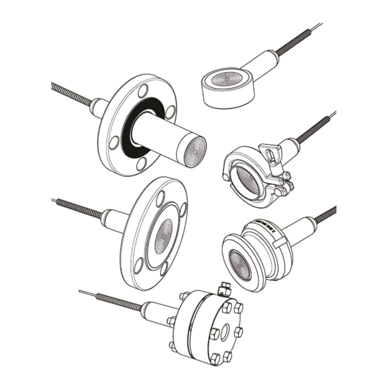
SR301 – Operation, Maintenance, and Instructions Manual Choosing the Ideal Assembly for Application Figure 2.1 shows the most common types of remote seal assembly and its applications. Figure 2.1 – Types of Remote Seal Assembly and Applications... -
Page 13: Transmitters Range For Remote Seal Application
LD30XL: Level Transmitter (Family 301, 302 and 303) LD30XS: Sanitary Transmitter (Family 301, 302 and 303) For more information, consult SMAR Pressure Transmitters Catalogs and Manuals. NOTE The overpressure shown in Table 2.3 above, does not damage the transmitter, although it will be necessary to recalibrate the transmitter. -
Page 14: Diaphragm Material
V. sup. –Work Range Upper Value V. inf – Work Range Lower Value Diaphragm Material The diaphragm material should be selected considering its chemical resistance to external agents, process fluid and temperature involved. For more information about materials corrosion, consult the Smar’s Application Engineer. -
Page 15: Filling Fluids
Table 2.4 shows the filling fluids used by Smar with some physical properties and types of application. On Figures 2.3 and 2.4 the Steam Pressure curves (mmHg) are shown against the Temperature (°C) of these fluids. -
Page 16: Temperature Error Presented By Seal
SR301 – Operation, Maintenance, and Instructions Manual 1100 1100 1000 1000 (1 atm) 760 (1 atm) 760 Temperature (ºC) Temperature (ºC) - Syltherm800 ( - Fluorolube ( - Sillicone DC200 ( - Halocarbon ( - Krytox ( - Silicone DC704 (... -
Page 17: Calculation Of Temperature Errors
Selection Calculation of Temperature Errors Remote seal temperature errors are due to the volume variation of the filling fluid in the transmitter body, extension, capillary and remote seal. Following, the necessary information for the error calculation are described. Equations To obtain a volume variation for each leg of the remote seal, the temperature variation in the seal, in the capillary and in the transmitter body must be known and then insert the value in the equations below. -
Page 18: Determination Of The Seal/Level Error For High (H) Or Low (L) Sides
SR301 – Operation, Maintenance, and Instructions Manual Calibrated Span: Transmitter Calibration (mmH O @ 4 ºC) Diaphragm Material Factor *Only for capillary standard diameter (≈1.0 mm) ATTENTION The temperature of reference for adjustment is 25 C. The Errors in terms of the temperature occur with the deviation of the temperature beyond 25 °C. - Page 19 Table 2.5 below shows the diaphragm family in terms of the transmitter/seal model. Model LD301L LD301L LD/SR 301 S LD/SR 301 S (WITHOUT (WITH/ SR301T SR301E (WITHOUT/ SR301 R SR301P Diaphragm (WITH/ EXT) /EXT) EXT) EXT) Family 1.1/2" 1" —...
- Page 20 SR301 – Operation, Maintenance, and Instructions Manual The Table 2.6 below shows the value of the diaphragm reservoir volume (Vrdf) for each family. Vrdf Diaphragm Family (x 10 18.1 20.4 24.8 29.2 38.4 47.7 82.8 105.6 274.2 Table 2.6 – Diaphragm Volume The Table 2.7 below shows the value of the material factor (Fm) in function of the diaphragm...
- Page 21 Selection The Figure 2.6 shows the error of the remote seal in terms of the diaphragm total volume (V ) for total diaphragms of 0.05mm thick in 25°C. 1 10 × 1 10 × 0.01 − 1 10 × 0.01 Vtotal (cm3) Figure 2.6 –...
- Page 22 SR301 – Operation, Maintenance, and Instructions Manual The Figure 2.7 shows an error of the remote seal in terms of the diaphragm total volume (V ) for total diaphragms of 0.075mm thick in 25°C. 1 10 × 1 10 ×...
-
Page 23: Assembly Accuracy
Selection The Figure 2.8 shows an error of the remote seal in terms of the diaphragm total volume (V ) for total diaphragms of 0.1mm thick in 25°C 1 10 × 1 10 × 0.01 − 1 10 × 0.01 Vtotal (cm3) Figure 2.8 –... -
Page 24: Total Probable Assembly Error
SR301 – Operation, Maintenance, and Instructions Manual Total Probable Assembly Error The Total Probable Error (TPE) of the transmitter and seal/level assembly is a measure that involves all the probable error sources in this measurement, such as: transmitter accuracy, ambient temperature, static pressure, vibration and changes in the transmitter power supply. -
Page 25: Calculation Of Remote Seal Response Time
Selection Calculation of Remote Seal Response Time The response time is obtained through the equation 2.15, below: ⋅ listed (2.15) Where: Remote seal response time (seconds) : Response Time through the capillary length (seconds/meters) – See Table 2.10 listed Capillaty length (meters) NOTE The values obtained for the seal response time do not consider the response time of the transmitter. - Page 26 SR301 – Operation, Maintenance, and Instructions Manual Response Time in seconds/meter of capillary (s/m) 2.69E-01 3.99E-01 1.72E-01 1.09E-01 5.59E-02 2.16E-02 2.66E-01 3.08E-01 8.37E-02 3.38E-01 5.75E-01 2.84E-01 1.52E-01 8.89E-02 4.32E-02 4.46E-01 4.83E-01 1.19E-01 4.55E-01 9.29E-01 7.86E-01 2.23E-01 1.57E-01 1.19E-01 1.00E+00 9.85E-01 1.88E-01...
-
Page 27: Capillary Length
Selection Capillary Length The capillary length is a variable defined in terms of the application need, as for example, the tank height or distance of the remote point to be measured. To evaluate the maximum capillary length, three conditions must be fulfilled: 1) To check if the expanded or contracted volume relative to the initial volume of the corrugated is within Lower and Upper limits (VC and VC... - Page 28 SR301 – Operation, Maintenance, and Instructions Manual VCmax (10 x cm ) for 316L Stainless Steel Diaphragm # 0.05mm # 0.1mm 15.9 24.3 29.8 36.6 47.9 86.6 100.6 248.9 13.4 21.2 26.7 32.6 42.2 76.6 88.4 231.4 14.8 22.6 27.6 34.0...
- Page 29 Selection VCmax (10 x cm ) for Tantalum Diaphragm # 0.05mm # 0.1mm 13.9 21.3 25.9 32.0 42.0 75.8 88.3 216.4 11.9 18.7 23.5 28.7 37.3 67.9 78.5 203.5 11.7 17.8 21.5 26.6 35.0 63.8 74.0 179.4 10.1 15.8 19.7 24.2 31.6 56.6...
- Page 30 SR301 – Operation, Maintenance, and Instructions Manual VCmax (10 x cm ) for Duplex Diaphragm # 0.05mm # 0.1mm 16.9 27.7 43.8 55.8 67.5 86.3 156.0 179.0 473.2 13.7 22.5 36.1 47.1 56.4 71.2 128.5 146.2 405.3 15.9 26.1 41.2 52.2...
-
Page 31: Error Guide Trend For Transmitter Assembled With Remote Seal
To better understand the influence of these parameters, a Total Probable Error behavior guide for the transmitter and the remote seal assembly was devised. This guide is valid only for the assembly of the Remote Seal SR301T and the Smar pressure transmitter LD30X with the following conditions: •... -
Page 32: Case 1 - Tpe % Of The Span With Calibration In Rangeability (1:1)
SR301 – Operation, Maintenance, and Instructions Manual Case 1 – TPE % of the Span with Calibration in Rangeability (1:1) Process Temperature: 40 ºC ± 0 ºC -> Δtp = + 15ºC Ambient Temperature: 25 ºC ± 0 ºC -> Δta = 0ºC... -
Page 33: Case 2 - Tpe % Of The Span With Calibration In Rangeability (1:1)
Selection Case 2 – TPE % of the Span with Calibration in Rangeability (1:1) Process Temperature: 100 ºC ± 0 ºC -> Δtp = + 75ºC Ambient Temperature: 40 ºC ± 0 ºC -> Δta = + 15ºC LD30XM (2 to 6) LD30XD (2 to 4) Capillary Range... -
Page 34: Case 3 - Tpe % Of The Span With Calibration In Rangeability (1:1)
SR301 – Operation, Maintenance, and Instructions Manual Case 3 – TPE % of the Span with Calibration in Rangeability (1:1) Process Temperature: 170 ºC ± 0 ºC -> Δtp = + 145ºC Ambient Temperature: 60 ºC ± 0 ºC -> Δta = + 35ºC... -
Page 35: Case 4 - Tpe % Of The Span With Calibration In Rangeability (10:1)
Selection Case 4 – TPE % of the Span with Calibration in Rangeability (10:1) Process Temperature: 40 ºC ± 0 ºC -> Δtp = + 15ºC Ambient Temperature: 25 ºC ± 0 ºC -> Δta = 0ºC LD30XM (2 to 6) LD30XD (2 to 4) Capillary Range... -
Page 36: Case 5 - Tpe % Of The Span With Calibration In Rangeability (10:1)
SR301 – Operation, Maintenance, and Instructions Manual Case 5 – TPE % of the Span with Calibration in Rangeability (10:1) Process Temperature: 100 ºC ± 0 ºC -> Δtp = + 75ºC Ambient Temperature: 40 ºC ± 0 ºC -> Δta = + 15ºC... -
Page 37: Case 6 - Tpe % Of The Span With Calibration In Rangeability (10:1)
Selection Case 6 – TPE % of the Span with Calibration in Rangeability (10:1) Process Temperature: 170 ºC ± 0 ºC -> Δtp = + 145ºC Ambient Temperature: 60 ºC ± 0 ºC -> Δta = + 35ºC LD30XM (2 to 6) LD30XD (2 to 4) Capillary Range... - Page 38 SR301 – Operation, Maintenance, and Instructions Manual 2.28...
-
Page 39: Chapter 3 - Operation
Chapter 3 OPERATION Operation of the Remote Seal Sensor In the remote seal transmitter, the remote insulator diaphragm plus transmission capillary set is connected to the transmitter chamber. The internal spaces of the capillary pipe diaphragm and the sensor chamber are filled with the application proper fluid, according to the pressure and the of the process operation temperature. -
Page 40: Range Beginning Change
SR301 – Operation, Maintenance, and Instructions Manual Figure 3.1 – Ascendant Curve of the Ix Output Signal in Terms of the Pressure P r e s s u re Figure 3. 2 - Descendant Curve of the Ix Output Signal in Terms of the Pressure (Reverse... -
Page 41: Level Transmitter Span Change
Operation Level Transmitter Span Change Proceed as for differential and flow transmitters. The span is given in Table 3.1. OUTPUT ZERO SPAN Pi = Hi . ∗p Ps = Hs . ∗p Ascendant Descendant Pi = Hs . ∗p Ps = Hi . ∗p Table 3.1 –... - Page 42 SR301 – Operation, Maintenance, and Instructions Manual...
-
Page 43: Chapter 4 - Maintenance
Return of Materials If it becomes necessary to return the transmitter and/or configurator to Smar, simply contact our office, informing the defective instrument's serial number, and return it to our factory. To speed up analysis and solution of the problem, the defective item should be returned with the Service Request Form (SRF –... -
Page 44: Remote Seal Spare Parts
SR301 - Operation & Maintenance Instructions Manual Remote Seal Spare Parts Sanitary Model Figure 4.2 – Sectional view SR301S 400-1331 SANITARY SEALING RING Option Mounting Without Extension With Extension Option Nominal Diameter DN25 DN40 1 ½” DN50 2” DN80 3”... - Page 45 Maintenance 400-1332 SANITARY TANK ADAPTER Option Mounting Without Extension With Extension Option Nominal Diameter DN25 DN40 1 ½” DN50 DN80 2” 3” Option Connection Tri-clamp 400-1331 400-1333 TRI-CLAMP Option Diameter 1 ½” 2” 3” Option Pressure HP (High pressure) Standard 400-1333...
- Page 46 SR301 - Operation & Maintenance Instructions Manual Flanged “T” Type and Pancake Models Sealing Sealing Sealing Gasket Gasket Gasket Housing Housing Housing Drain Valve Drain Valve Drain Valve MOUNTING WITH MOUNTING WITH MOUNTING WITH FF FLANGE PANCAKE RF FLANGE Figure 4.3 – Sectional View - Mounting with Gasket and Drain Valve SEALING GASKET FOR FLANGE ASME/DIN –...
- Page 47 Maintenance RTJ SPARE PARTS: LD300L (without Extension) / SR301T / SR301E DRAIN METALLIC RING VALVE ØN CLASS STANDARD RING STAINLESS STAINLESS STEEL 316L STEEL 316L 400-0887 400-0888 1” 400-0888 1500 400-0888 2500 400-0889 400-0890 400-0891 1.1/2” 400-0891 1500 400-0891 2500 400-0893 400-0792 ASME B 16.20 RTJ...
- Page 48 SR301 - Operation & Maintenance Instructions Manual Threaded Model SR301R SPARE PARTS DRAIN SEALING GASKET VALVE THREAD STAINLESS TEFLON GRAFOIL STEEL 316L 1/4” 3/8” 1/2” 201-0120 400-0459 400-0792 3/4” 1” 1.1/2” Table 4.2 – SR301R Spare Parts NOTE The gasket is common for the 138 bar and 400 bar versions.
-
Page 49: Chapter 5 - Examples
Chapter 5 EXAMPLES NOTE For the examples on this Chapter, consider the calibrated seal at temperature of 25°C. Example 1 Considering a Two-Seal Transmitter. A – TRANSMITTER DATA RESPONSE Type of Transmitter (Absolute, Gauge, Differential) Differential Range Superior Value / (V.sup.) (mmH2O @ 4 ºC) 2400 Range Inferior Value / (V. - Page 50 SR301 – Operation & Maintenance Instructions Manual C – ASSEMBLY SCHEME LOW SIDE HIGH SIDE CAPILLARY CAPILLARY TRANSMITTER T BODY MAX H T CAP MAX H T SEAL MAX H T SEAL MAX L T CAP MAX L T BODY MAX L...
-
Page 51: Error Calculation By Temperature
Examples Error Calculation by Temperature Have: 1º – “Upper Variation of Temperature” Seal H Side ∆ − º seal ∆ − º ∆ − º body Using the formulas on Chapter 2, item 2 we have: ∆ 0508 ∆ 0049 ∆... - Page 52 SR301 – Operation & Maintenance Instructions Manual 9000 NOTE If the diaphragm is equal to 0.1mm enter this value V on Figure 2.8, E = + 80.2060 mmH total 2º – “Temperature Lower Variation” Seal H Side ∆ − º...
-
Page 53: Calculation Of Seal/Level Error
Examples Seal L Side ∆ − º seal ∆ − − − º ∆ − − − º body Using the formulas from Chapter 2, item 2: ∆ 0620 ∆ 0060 ∆ − 1300 ∆ − 0494 body ∆ − 1113 total total... -
Page 54: Calculation Of The Transmitter Accuracy With Seal/Level
SR301 – Operation & Maintenance Instructions Manual 8128 2º – “Lower Temperature Variation” − 4160 − 7080 3205 Calculation of the Transmitter Accuracy with Seal/Level NOTE The transmitter accuracy is not significantly altered by the addition of seal/level. However, the measuring error resulting from the combination suffers significant increase due to physical and geometric parameters, in terms of temperature variation. -
Page 55: Calculation Of The Response Time
Examples Calculation of the Response Time ⋅ The response time is obtained through the Equation 2.14: listed Considering that the transmitter is range 2 type, the filling fluid is DC200/20. However, the temperature to be used is closer to the Maximum value, because the temperature will not necessarily be kept on the maximum. - Page 56 SR301 – Operation & Maintenance Instructions Manual Table 2.18 shows the VC value. Considering that the assembling was performed with a range 2 transmitter, the value relative to is obtained by the linear interpolation between 50% and 40%, whereby: −...
-
Page 57: Example 2
Examples Example 2 Combining Geometric Symmetry with Thermal Symmetry to minimize the Error. A – TRANSMITTER DATA RESPONSE Type of Transmitter (Absolute, Gauge, Differential) Differential Range Superior Value (V.sup.) (mmH2O @ 4 ºC) 2400 Range Inferior Value (V. inf.) (mmH2O @ 4 ºC) -1000 Transmitter Calibration (Span) (mmH2O @ 4 ºC) - Page 58 SR301 – Operation & Maintenance Instructions Manual C – ASSEMBLY SCHEME LOW SIDE HIGH SIDE CAPILLARY CAPILLARY TRANSMITTER T SEAL MAX L T CAP MAX L T BODY MAX L T BODY MAX H T CAP MAX H T SEAL MAX H...
-
Page 59: Error Calculation By Temperature
Examples E – USER EXPECTANCY RESPONSE 1. Global Error Requested by User (% Transmitter Calibration) 0.5% 2. Response Time Requested by the Mesh Control (seconds) Table 5.10 – User Expectancy (Example 2) Error Calculation by Temperature Have: 1º – “Upper Variation of Temperature” Seal L and H Side ∆... -
Page 60: Calculation Of The Transmitter Accuracy With Seal/Level
SR301 – Operation & Maintenance Instructions Manual Calculation of the Transmitter Accuracy with Seal/Level NOTE The transmitter accuracy is not significantly altered by the addition of seal/level. However, the measuring error resulting from the combination suffers significant increase due to physical and geometric parameters, in terms of temperature variation. -
Page 61: Checking The Capillary Length
Examples Maximum Temperature on the L Side Capillary, 30°C, from the Table 2.9: listed listed Thus: × 1410 NOTE Note that the response time between the sides is smaller than 0.5 second and therefore this type of assembling is recommended. 2820 This response time refers only to the remote seal. - Page 62 SR301 – Operation & Maintenance Instructions Manual − ⋅ From the calculation: (“Upper Temperature Variation”) total total − (“Lower Temperature Variation”) total total All the values are in their lower and upper limits according to equation 2.12, which makes the first condition acceptable.
-
Page 63: T" Type Flanged Remote Seal - Sr301T
Chapter 6 TYPE OF SEAL AND ORDERING CODE “T” Type Flanged Remote Seal - SR301T Description The SR301T is a flanged seal with welded diaphragm. It can be supplied with an optional flush connection and housing. The flush connection removes deposits of the diaphragm without disconnecting the seal. -
Page 64: Flanged Remote Seal With Extension - Sr301E
(1) Fluorolube Filling Fluid is not available with Monel Diaphragm. (2) Supplied Without Gasket. (3) Standard DIN EN 1092-1 subdivides DN80 into PN16 (c=20) and PN40 (c=24), Smar provides only PN40 (c=24), external diameter and holes coincide. (4) Also fits the #900 class. - Page 65 Notes – SR301E: (1) Fluorolube Filling Fluid Is Not Available with Monel Diaphragm. (2) Standard DIN EN 1092-1 subdivides DN80 into PN16 (c=20) and PN40 (c=24), Smar provides only PN40 (c=24), external diameter and holes coincide. (3) Item by inquiry.
-
Page 66: Threaded Remote Seal - Sr301R
SR301 - Operation & Maintenance Instructions Manual Threaded Remote Seal – SR301R Description The SR301R is a threaded connection seal. The diaphragm is welded to the flange. This model is always supplied with housing because the process thread is located in this part. The (optional) flush connection in the housing enables to remove deposits on the diaphragm without disconnecting the seal. -
Page 67: Sanitary Remote Seal - Sr301S
Type of Seal and Ordering Code Sanitary Remote Seal – SR301S Description The SR301S is a seal for food and other applications where the sanitary connections are necessary. The diaphragm is welded to the connection face, which can be Threaded type or Tri-Clamp, allowing an easy and fast connection/disconnection of the process equipment. -
Page 68: Pancake Remote Seal - Sr301P
SR301 - Operation & Maintenance Instructions Manual Pancake Remote Seal - SR301P Description The SR301P is a seal with welded diaphragm, whose assembly requests blind flanges. This model is supplied with housing and flush connection (optional). The flush connection removes deposits on the diaphragm without disconnecting the seal. -
Page 69: Technical Data
Type of Seal and Ordering Code Technical Data The calibration maximum limit of the remote seal or level transmitter should be the smallest value between the connection pressure limit (see following tables) and the upper range limit of the transmitter (URL). See transmitter’s manual. PRESSURES TABLE FOR SEAL AND LEVEL FLANGES ASME B16.5 2017 STANDARD Maximum Temperature Allowed Material... - Page 70 SR301 - Operation & Maintenance Instructions Manual PRESSURES TABLE FOR SEAL AND LEVEL FLANGES DIN EN 1092-1 2008 STANDARD Maximum Temperature Allowed Material Pressure Group Class Maximum Pressure Allowed (bar) PN 16 13.7 12.3 11.2 10.4 PN 25 21.5 19.2 17.5...
- Page 71 Type of Seal and Ordering Code Pressure Limit Tri-Clamp (TC) (Bar) – Table 1 Normal Pressure High Pressure (HP) 20°C (68ºF) 120°C (248ºF) 20°C (68ºF) 120°C (248ºF) 1.1/2" 2" / DN50 3" Pressure Limit for Thread (Bar) – NP – Table 2 120°C (248ºF) 120°C (248ºF) 120°C (248ºF)
- Page 72 SR301 - Operation & Maintenance Instructions Manual O’Ring Materials Guide – Table 4 Ambient Teflon® (PTFE) Viton Buna N Acetic Acid, 30% S.I. Acetone Air, below 93 ºC (200° F) ++++ ++++ ++++ Ammonia Gas, Cold ++++ ++++ Ammonia Gas, Hot...
-
Page 73: Diaphragm Hydrogen Migration
Type of Seal and Ordering Code Diaphragm Hydrogen Migration The hydrogen in H2 form does not have penetration danger in the diaphragm. However if the hydrogen separates forming ions of hydrogen (H+), the penetration can happen, therefore the spaces between the molecules of the diaphragm material can be larger than the size of the ion. Inside of the diaphragm, this ion in contact with filling fluid (silicone oils) can be return the H2 form and to be arrested (inflating the diaphragm), causing damages the measurement. -
Page 74: Application With Halar For Seals And Levels
SR301 - Operation & Maintenance Instructions Manual Application with Halar for Seals and Levels Technical Specification Halar® is chemically one of the most resistant fluoropolymers. It is a thermoplastic of the melting process manufactured by Solvay Solexis, Inc. For its chemical structure, a 1:1 alternating ethylene copolymer and chlorinetrifluoroethylene, Halar®... -
Page 75: Tpe - Total Probable Error (Software)
TPE was developed to a fast and effective aid of the products related the pressure measurement. The users are the Applications Engineer and Commercial Areas. The customer can request a report of performance estimate to Smar. This product allows doing simulations of possible assemblies, verifying important data as the error estimates of the response time, of capillary length analysis and mechanical resistance of diaphragms with temperature variation. -
Page 76: Dimensions
SR301 - Operation & Maintenance Instructions Manual Dimensions SR301T (RF/FF/RTJ) - “T” Type Flanged Remote Seal and SR301E (RF/FF/RTJ) - Flanged Remote Seal with Extension (Integral Flange) 6.14... - Page 77 Type of Seal and Ordering Code 6.15...
-
Page 78: Sr301R - Threaded Remote Seal
SR301 - Operation & Maintenance Instructions Manual SR301R – Threaded Remote Seal 6.16... -
Page 79: Sr301P - Pancake Remote Seal Without Extension
Type of Seal and Ordering Code SR301P – Pancake Remote Seal without Extension 6.17... -
Page 80: Lower Housing
SR301 - Operation & Maintenance Instructions Manual Lower Housing 6.18... -
Page 81: Sr301S - Sanitary Remote Seal With Extension
Type of Seal and Ordering Code SR301S – Sanitary Remote Seal with Extension Dimensions see Table 5 6.19... -
Page 82: Sr301S - Sanitary Remote Seal Without Extension
SR301 - Operation & Maintenance Instructions Manual SR301S – Sanitary Remote Seal without Extension Dimensions see Table 5 6.20... - Page 83 Type of Seal and Ordering Code Table 5: Dimensions relative to pages 6.19 and 6.20. 6.21...
- Page 84 SR301 - Operation & Maintenance Instructions Manual 6.22...
-
Page 85: Appendix A - Service Request Form
(Please, describe the failure. Can the error be reproduced? Is it repetitive?) OBSERVATIONS USER INFORMATION Company: Contact: Title: Section: Phone: Extension: E-mail: Date: Signature: For warranty or non-warranty repair, please contact your representative. Further information about address and contacts can be found on https://www.smar.com/en/support... - Page 86 SR301 – Operation, Maintenance, and Instructions Manual...
Need help?
Do you have a question about the SR301 and is the answer not in the manual?
Questions and answers