Table of Contents
Advertisement
Quick Links
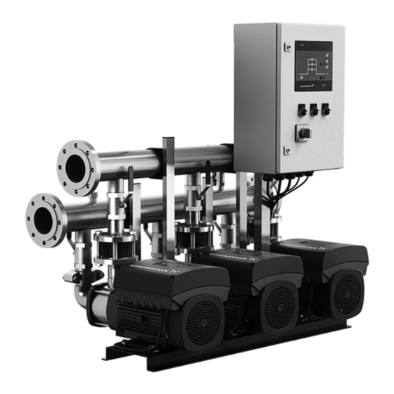
Hydro Multi-B
Pressure boosting and tank fill applications
Installation and operating instructions
GRUNDFOS INSTRUCTIONS
The Pacific Northwest's
premier Grundfos CBS
Manufacturer's Representative
for all Grundfos Booster
systems. Hurley Engineering
offers complete start up,
selection & installation
assistance, and has a full staff
of service technicians available
for preventive maintenance
programs. Hurley Engineering
is also the Pacific Northwest's
only Grundfos CBS Authorized
Service Partner.
Advertisement
Table of Contents

Subscribe to Our Youtube Channel
Related Manuals for Grundfos HURLEY ENGINEERING Hydro Multi-B Series

Summary of Contents for Grundfos HURLEY ENGINEERING Hydro Multi-B Series
- Page 1 Pressure boosting and tank fill applications Installation and operating instructions The Pacific Northwest's premier Grundfos CBS Manufacturer's Representative for all Grundfos Booster systems. Hurley Engineering offers complete start up, selection & installation assistance, and has a full staff of service technicians available for preventive maintenance programs.
-
Page 2: Table Of Contents
Other important notes Products manufactured by GRUNDFOS PUMPS CORPORATION Receiving the product (Grundfos) are warranted to the original user only to be free of Transporting the product defects in material and workmanship for a period of 24 months Installing the product... -
Page 3: Symbols Used In This Document
2. Symbols used in this document 4. Installing the product Before installing the product, check the following: 2.1 Warnings against hazards involving risk of death • The booster system corresponds to the order. or personal injury • All visible parts are intact. DANGER 4.1 Location Indicates a hazardous situation which, if not avoided,... - Page 4 4.2.2 Foundation Position the booster system on an even and solid surface, for instance a concrete floor or foundation. The booster system must be bolted to the floor or foundation. The weight of a concrete foundation must be 1.5 times the weight of the booster system. 4.2.3 Vibration dampers To prevent the transmission of vibrations to buildings, it may be necessary to isolate the booster system foundation from building...
-
Page 5: Electrical Installation
5. Starting up the product Expansion joints with limiting rods can be used to minimise the forces caused by the expansion joints. We always recommend that you use expansion joints with limiting rods for flanges larger A positive inlet pressure is required before startup than ANSI 4"... -
Page 6: Flooded Suction And Suction Lift Startup Procedures
5.2 Flooded suction and suction lift startup 5.3 Handling the product procedures Lift the booster systems with CM and CME pumps as shown in fig. 4. 1. Check that the precharge pressure in the diaphragm tank is 0.7 times the required outlet pressure (setpoint). During handling, the lifting point must always be above the center Note: Set the precharge pressure with zero pressure on the of gravity of the booster system. -
Page 7: Product Introduction
6. Product introduction 6.2 Applications The booster systems are suitable for the following application 6.1 Product description types: Hydro Multi-B is a range of factory-assembled pump systems, • constant-pressure boosting ready for installation and operation. • tank filling. As standard, the booster systems consist of two and three pumps 6.2.1 Booster system for constant-pressure applications connected in parallel and mounted on a common base frame with a control cabinet and all necessary fittings. - Page 8 The PC tool is required to adjust the start and stop the user interface of the CU 323 control unit. level setting. For assistance contact Grundfos. The Multi-B systems configured for tank filling applications work as described below. Control variant E...
-
Page 9: Identification
6.3 Identification 6.3.1 Nameplate The nameplate of the booster system is fitted on the base frame. Type: HYDRO MULTI-B 3 CME10-3 Model: A Serial No.: 10000001 Mains supply: 3 x 460 V, 60 Hz pMax: 145 PSI Q Nom / Max: 159 / 240 Liq. -
Page 10: Control Unit
7. Control unit The booster system incorporates a CU 323 control unit which enables manual setting and monitoring of the system. Figure shows the user interface for a system with four pumps. CU 323 CU 323 AUTO AUTO AUTO AUTO AUTO RESET system run... - Page 11 Pos. Buttons Description "Measured value" Shows the actual, measured value on the outlet side. Proportional setpoint at zero flow, PPS [psi]. "PPS" is visible if you press [RESET] for four seconds. After [RESET] has been released, you can adjust "PPS" by means of the arrow up or arrow down buttons.
-
Page 12: Operating Modes
8. Operating modes User operation depends on the system mode. The system modes are described in the following sections. 8.1 Local mode, external stop not activated In this mode, the system is locally controlled, and the external stop via digital input is not activated. The flow charts below show examples of how settings can be made. -
Page 13: Remote-Controlled, External Stop Not Activated
Changing the setpoint Changing the setpoint If you do not touch the buttons for 3 seconds, CU 323 reverts to the initial display. 8.2 Remote-controlled, external stop not activated In this mode, the system is remote-controlled, and the external stop via digital input is not activated. If you want to change the local settings, follow the flow chart examples below. -
Page 14: Adjusting The Proportional-Pressure Setpoint
8.4 Adjusting the proportional-pressure setpoint The function has these purposes: • compensate for pressure losses Description • reduce the energy consumption You can only enable this function in pressure-controlled systems. • increase the comfort for the user. The function automatically adapts the setpoint to the actual flow rate to compensate for flow-dependent dynamic losses. -
Page 15: Functions
The limit for the minimum inlet pressure in the inlet manifold is a pumps is running. This means that the number of running pumps factory-set value which can only be changed by a Grundfos always corresponds to the required flow at the entered setpoint. - Page 16 Start/stop band The status as standby pump alternates between all pumps. Hset Contact Grundfos for further information. Pump starts 9.2.3 Maximum pressure exceeded This function protects the piping on the outlet side of the booster Time [s] system against damaging high pressures.
-
Page 17: Functions For Tank-Filling Systems
Take individual pumps out of operation by switching off the Various CIM modules are available, depending on the type of corresponding motor-protective circuit breaker, automatic circuit network. See the Hydro Multi-B data booklet or contact Grundfos breaker or fuse. for further information regarding CIM modules. -
Page 18: Fault Finding
The main switch has cut out. Cut in the main switch. d) The main switch is defective. Replace the main switch. e) The motor protection has been Contact Grundfos. activated. The motor is defective. Repair or replace the motor. g) The pressure transmitter is defective. -
Page 19: Technical Data
NPSH can be read from the NPSH curve at the maximum capacity at which the pump will run. 0-20 mA Input current and voltage 4-20 mA See Grundfos CM, CME Data booklet 98435269 / L-CM-PG-001. 0-10 V Safety margin = minimum 2 feet Tolerance ± 3.3 % of full scale Repetitive accuracy ±... -
Page 20: Related Documents
17. Disposing of the product This product or parts of it must be disposed of in an environmentally sound way: 1. Use the public or private waste collection service. 2. If this is not possible, contact the nearest Grundfos company or service workshop. - Page 21 Grundfos Kansas City Grundfos Canada Grundfos México 17100 West 118th Terrace 2941 Brighton Road Boulevard TLC No. 15 Olathe, Kansas 66061 Oakville, Ontario L6H 6C9 Canada Parque Industrial Stiva Aeropuerto Phone: +1-913-227-3400 Phone: +1-905 829 9533 C.P. 66600 Apodaca, N.L. Mexico...
- Page 22 98504518 1117 ECM: 1220792 www.grundfos.com www.grundfos.us...
Need help?
Do you have a question about the HURLEY ENGINEERING Hydro Multi-B Series and is the answer not in the manual?
Questions and answers