Advertisement
Quick Links
WARNING
sales@agrotkindustrial.com
PRODUCT MANUAL
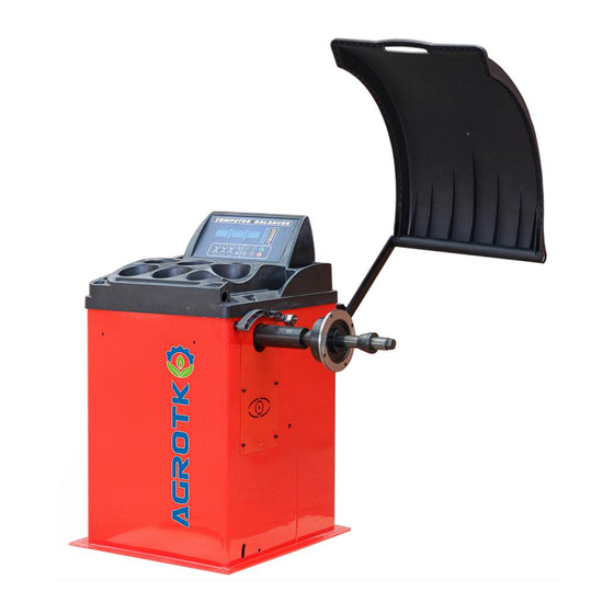
AG T - W B 24 Whe e l Ba l a n c e r
This manual is an integral part of this product, pls read carefully
to prevent any danger of misoperation!
Keep this manual well for future further maintenance.
This machine is only used for wheel balancing, not for other
purposes.
Pleasecontact
sales@agrotkindustrial.com
https://www.agrotkindustrial.com/
https://www.agrotkindustrial.com
/
1
Advertisement

Summary of Contents for AGT INDUSTRIAL AGT-WB24
- Page 1 PRODUCT MANUAL AG T - W B 24 Whe e l Ba l a n c e r WARNING This manual is an integral part of this product, pls read carefully to prevent any danger of misoperation! Keep this manual well for future further maintenance. ...
- Page 2 DO’S AND DONT’S ● The machine must be operated by specially trained and qualified personnel. Any modification of the machine parts and out of scope of use, without the permission of the manufacturer or the requirements of the manual, may cause direct or indirect damage to the machine.
- Page 3 TABLE OF CONTENTS 1. overview------------------------------------------------------------------------------------------------------------------------------------1 2. installation --------------------------------------------------------------------------------------------------------------------------------4 3. machine introduction-------------------------------------------------------------------------------------------------------------------5 4. operation -------------------------------------------------------------------------------------------------------------------------------7 5. calibration ------------------------------------------------------------------------------------------------------------------------------13 6. trouble description --------------------------------------------------------------------------------------------------------------------14 7. trouble shooting------------------------------------------------------------------------------------------------------------------------14 8. parameter setting----------------------------------------------------------------------------------------------------------------------16 9. OPT program------------------------------------------------------------------------------------------------------------------------ ----17...
- Page 4 ONE. overview The poor dynamic balance of wheels will make the running wheels jump and the steering wheel vibrate, which will affect the driver' s driving, leading to increase gap of the joint part of the steering system, damage the shock absorber and steering parts, and increase the probability of traffic accidents.
- Page 5 TWO. Installation 1.machine installation The equipment must be installed on a solid cement floor or similar. If the ground is not solid, measurement error will be caused. There should be space around the equipment for easy operation. See below: Note: This diagram does not represent the form factor of the equipment you actually purchased, and this figure is for installation location reference only.
- Page 6 1.display unbalance value inner 2. display inner unbalance position indication stripe 3. display unbalance value outer 4. display outer unbalance position indication stripe 5. balance mode indicator,it can realize the following balance mode: figure operation method explanation balance mode standard 1.
- Page 7 paste the unbalanced block on 1. turn on the machine 2.input a,b,d value the alignment plane inner, and ALU5 balance clip the unbalanced block at 3. press the ALU key to turn on mode the mode light outer. 4. start, wait until it stops 1.
- Page 8 conform to specified value. Check if there is any deformation on rim locating surface and mounting hole. According to the wheel rim structure, select the appropriate tire installation method. Choose the following two installation methods according to the wheel rim structure: main shaft—...
- Page 9 Pic.3 Slowly rotate the tire counterclockwise by hand until the indicator light inner is all on. At this point, the highest point (12 o ' clock) on the inner rim is the correct point of unbalance. Add corresponding weight lead at this position. See pic. 4 Pic.4 8)After the weight lead is all placed on,press key to rotate the wheel,if no mistake during operation, pic.
- Page 10 Pic.6 6) turns slowly the tires counterclockwise, until the inner side of the indicator lights are all on, at the point at 12 o 'clock(12H is off) or 9 o 'clock (9H is on) are the unbalance point of alignment planes. Balance alignment planes are as shown in below pictures.
- Page 11 through input (automatic measurement is optional). diameter (d) value :automatically read it from the rim ,input through Pic.9 2) put down the hood and press key,then the main shaft start to rotate 3 There are two ways to check the unbalanced result 3 .1 set the option SLC to OFF.
- Page 12 Pic.12 set the option SLC to ON ( ( With automatic gauge function, you can use the gauge head to find position to stick the block) Pic.13 4.1 rotate slowly the tire anticlockwise by hand until the outside of indicator lights are all on (Pic.14), Pic.14 4.2 Tear out the suitable weight lead(Pic.15) and place it on head of ruler (Pic.16),...
- Page 13 Pic.18 4.5 Rotate slowly the tire anticlockwise by hand until the inside of indicators lights are all on (Pic.19) Pic.19 4.6 Tear out the suitable weight lead(Pic.15) and place it on head of ruler (Pic.16)),pull out the ruler until to see the position of inner unbalance point on rim inside (Pic.20) Pic.20 4.7 Paste the weight lead on the tire,Pic.21...
- Page 14 display> In case of ALU-S mode unbalanced weight is come out,press display> Input quantity of spokes by ,then press display> Hold one of the spokes on the rim at 12 O'clock ,then press Slowly turn the tire counterclockwise until the outer side of unbalanced SP1 indicator lights are all on ( the unbalanced position is determined display>...
- Page 15 Distance ruler calibration optional function No automatic gauge, no calibration required. display > display key to confirm Pull out the ruler to zero position and press > display Pull out the ruler to 15 position and press key to confirm >...
- Page 16 1 .Tire is with no pressure. 1 .Mounting the tire and inflate it. .Tire distortion is out of range 2 .Check the tire. 1. Position sensor is something wrong. 1. Check or replace position sensor 2. Computer panel is something wrong. 2.
- Page 17 Operation setup ★in normal standby mode, press key, at meanwhile press key to enter in, are used for amending, key is for next item. ★The machine has the following functions, which can be adjusted according to your own requirements。 Function Screen displayed option Function definition...
- Page 18 NINE OPT program This function can be performed when the unbalance weight is too big or the rim is deformed Select the appropriate installation mode according to the rim shape and input rim data display Press > display Put down the hood,press >...
Need help?
Do you have a question about the AGT-WB24 and is the answer not in the manual?
Questions and answers