
Summary of Contents for Dunlop DL240B+
- Page 1 DL240B+ Installation, Operating and Service Manual ALWAYS KEEP Read the operating instructions before operating instructions ready to hand on the working with the unit unit Date: 23/06/2023...
- Page 2 Before taking into operation check system compo- nents, control, emer- gency stop and safety equipment for conditi- on, damage and correct function! Please read this manual before you get started. You must read and understand the precautions for safety purposes and any damages that may occur to your property.
-
Page 3: Table Of Contents
INDEX GENERAL INFORMATION..................................5 1 – TECHNICAL DATA ..................................... 7 1.1 LIFT DESCRIPTION ..................................8 1.2 LAYOUT ......................................9 1.3 LOAD DISTRIBUTION ................................... 10 1.4 PICTOGRAMS....................................11 1.4 PICTOGRAMS APPLICATION DIAGRAM ............................. 12 1.5 HAZARDOUS AREAS ................................... 12 2 - FOREWORD ...................................... 14 2.1 EC CERTIFICATION .................................. - Page 4 BEFORE STARTING TO OPERATE WITH THE BRIDGE READ CAREFULLY THE INSTRUCTIONS CONTAINED IN THIS MANUAL THIS USER'S MANUAL IS WRITTEN IN THE MANUFACTURER'S LANGUAGE, AND IN OTHER COMMUNITY LANGUAGES. IN CASE OF COMPLAINT, FORLEGAL PURPOSES, THE VERSION IN ITALIAN LANGUAGE ONLY WILLAPPLY.
-
Page 5: General Information
GENERAL INFORMATION His chapter contains warning instructions to properly operate the lift and prevent injury to operators or property. This manual has been written to be used by workshop technicians in charge of the lift (OPERATOR) and routine maintenance technician (MAINTENANCE OPERATOR). The operating instructions are considered to be an integral part of the machine and must remain with it for its whole useful life. - Page 6 WARNINGS Unauthorized changes and/or modifications to the machine relieve the manufacturer from any liability for possible damage to objects or people. Do not remove or make inoperative the safety devices, this would cause a violation of law and regulations on safety at work. Any other use which differs from that provided for by the manufacturer of the machine is strictly forbidden.
-
Page 7: Technical Data
1 –TECHNICAL DATA BASIC MODEL Max. capacity 4000 Lifting time when loaded Lowering time when loaded Minimum height Lifting height 2045 Distance between the columns 2800 Lift max. height 3415 Volt-Hz- Three-phase electric motor 230V/400V/50/60Hz -8.2 Three-phase motor power kW/HP Volt-Hz- 220V –... -
Page 8: Lift Description
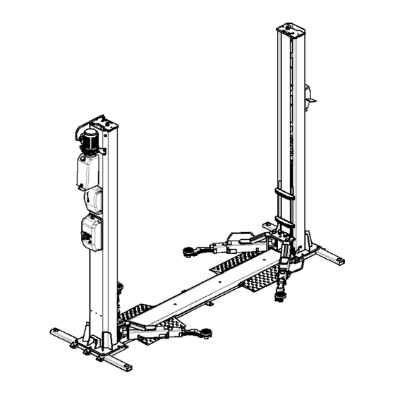
1.1 LIFT DESCRIPTION DESCRIPTION OF THE LIFT 1. P1 Column 11. Up push-button 2. P2 Column 12. Down push-button 3. P1 Carriage 13. Safety device push-button 4. P2 Carriage 14. Hydraulic power unit 5. 3 Stage long lifting arm 15. Control panel 7. -
Page 9: Layout
1.2 LAYOUT... -
Page 10: Load Distribution
1.3 LOAD DISTRIBUTION... -
Page 11: Pictograms
1.4 PICTOGRAMS... -
Page 13: Hazardous Areas
1.5 HAZARDOUS AREAS Operator Area... -
Page 14: Foreword
2 - FOREWORD This manual includes the instructions relating to the installation, use and maintenance of the lift system called "Vehicle Lift". The vehicle lifts described in this manual are designed and constructed solely to lift vehicles for repair, maintenance and inspection purposes. Lift operation, economy and duration depend on the compliance with the instructions given in this manual. -
Page 15: General Safety And Accident-Prevention Rules
3 - GENERAL SAFETY AND ACCIDENT-PREVENTION RULES FOR A SAFE USE OF THE VEHICLE LIFT DESCRIBED IN THIS MANUAL THE FOLLOWING IS ALLOWED: Using lift only to lift vehicles for inspection, maintenance and/or repair operations. Using lift only to lift vehicles respecting capacity limits and loads distribution indicated in this manual. Only authorized personnel, in good health conditions, responsible and duly trained on the allowed uses and risks originated by lift use may operate the lift. -
Page 16: Set-Up And Clothing
3.1 SET-UP AND CLOTHING Set up a space suitable for the machine, and the working environment, by carefully evaluating the following aspects: • The position shall be safe, free from any hinder, and protected against atmospheric agents. From the control position, the operator shall be able to see the whole system and the working area, and to immediately detect the presence of unauthorized persons and objects that could originate any danger. -
Page 17: Hazardous Areas
3.5 HAZARDOUS AREAS Before using the lift, make sure that no unauthorized persons nor animals are present within the hazardous area delimited by the yellow stripe. Persons or animals shall by no means stop or pass within the hazardous area delimited by the yellow stripe, when using lift even for small movements, and whenever the Emergency Switch/OFF is not depressed. -
Page 18: Transport And Installation
4 – TRANSPORT AND INSTALLATION Since the lift is packed in a special wooden crate, it can only be handled using a pallet truck or fork-lift truck, fitting the forks into the slots as shown in figure 2. Packing dimensions 510 mm 842 mm 2870 mm... -
Page 19: Installation
Concrete class 32mpa. Reinforcement Fe B 44 K. The lift must be fixed to this surface using heavy-duty anchor fixtures as described in the “Anchor Bolt Installation Procedure” section of the manual. The said surface must be capable of supporting at least 25 Kg/cm2 and have a strength rating of at least 32mpa. The layer of concrete must be sufficient to ensure effective installation of the anchor bolts, and have a good structure to a depth of at least 200 mm. - Page 20 WARNING The manufacturer declines liability for any damages resulting from failure to follow the above instructions, which may invalidate the warranty.
-
Page 21: Connecting To The Electricity Mains
4.4 CONNECTING TO THE ELECTRICITY MAINS The lift must be connected to the mains electricity supply by the customer. To connect to the electricity supply, use a 3 core + earth cable with cross section of 2.5 mm2 for the 380V version; To connect to the electricity supply, use a 2 core + earth cable with cross section of 2.5 mm2 for the 220V version The cable must be completed with a main plug of the type in use in the country where the lift is installed. -
Page 22: Electricalhook Up On The Control Panel
WARNING The manufacturer declines liability for any damages resulting from failure to follow the above instructions, which may invalidate the warranty. Before supplying power to the lift, make the following checks: • Check that the power supply voltage and frequency correspond to the values stated on the rating plate. •... - Page 23 4.5.2 Upper Limit Device ATTENTION:If you need to connect the upper limit switch, remove the wires on12 # and13 # and connect the upper limit switch to the 12 # and 13 # terminals.
-
Page 24: Electrical Hook Up Between The Two Pillars
4.6 ELECTRICAL HOOK UP BETWEEN THE TWO PILLARS To make the connection between the two pillars, proceed as follows: • Place the right-hand pillar in its definitive position and fix it to the floor; • Place the left-hand pillar in its definitive position and fix it to the floor; •... -
Page 25: Hydraulic Connection
4.7 HYDRAULIC CONNECTION The lift is partially assembled in the hydraulic part. To complete the hydraulic connection: • First position the fixing pipe[4] and fix the pipe to the place between the two flexible oil pipes[3] and [5] from pillar 1 and pillar 2, as shown in FIG.5; •... -
Page 26: Connection Cables Of Sync
4.8 CONNECTION CABLES OF SYNC To connect the synchronism cables between the two columns: a) Lift the arm to the position at half height and stop them in safe position. The two carriage must be perfectly aligned and positioned in the same rack of the guide; b) Remove the cable pulley in the bottom of pillar 1 with externa pliers, after installing cable a to the pulley, re- fix it with siegeers;... -
Page 27: Start Up
Adjustment of the arms looking Unscrew the screws A (see picture). near to the pin (marked-) or move away (marked +) until the gear engages properly. After adjustment, tighten the screws A. 4.9 CHECK THE MOTOR ROTATION DIRECTION Then lower the lift using the down button [12] switch on the control panel. The carriages must descend simultaneously. -
Page 28: Utilization
5.2 UTILIZATION The machine must only be used by authorized personnel. Use by personnel who are not familiar with the procedures specified in this manual could be dangerous. The operation of the machine is as follows: Vehicle positioning When positioning the vehicle over the pads, pay attention to the following recommendations: a) the total weight of the vehicle must not exceed 4000 kg b) place the vehicle on the pads, making sure that it is aligned and centered with respect to the longitudinal axis of the lift. -
Page 29: Emergency Procedures
WARNING The vehicle must only be lifted to the lifting points prescribed by the vehicle manufacturer. For assistance, contact authorized centers and request the use of original parts. 5.3 EMERGENCY PROCEDURES These modes are intended for handling emergency situations which may arise due to malfunction, incorrect loading, power failure, etc. - Page 30 STORAGE If the lift is to be out of use for a long period of time, it must be disconnected from the electricity supply and any parts which might be damaged by dust must be protected. ENVIRONMENTAL INFORMATION The disposal procedure described below must only applies to machines with the symbol of the waste bin with a bar across iton their rating plates This product may contain substances which may cause damage to the environment and human health if not disposed of properly.
-
Page 31: Troubleshooting
7 – TROUBLESHOOTING Problem Cause Solution The transformer primary mains switch is Take it to the on position. in the OFF position. The emergency switch QM located on the switchboard crankcase is in the OFF Take it to the on position. The Lift is connected to the position. -
Page 32: Schemes
8 - SCHEMES 8.1 COLUMN WIRING DIAGRAM... - Page 33 8.2 ELECTRICAL CABINET DIAGRAM(400V)
- Page 34 8.3 ELECTRICAL CABINET DIAGRAM(220V)
- Page 35 8.4ELECTRICAL DIAGRAM 380V - 3 PH...
- Page 36 8.5 LEGEND LEGEND FUSE WHITE LIGHT MAIN SWITCH UP BUTTON CONTACTOR FC1/2 LIMIT CHAIN MOTOR DOWN BUTTON TRANSFORMER DOWN SAFETY FUSE ELECTROMAGNETIC FUSE DOWN E。V FUSE EM1/2 ELETROMAGNETIC RECTIFIER BRIDGE TIME RELAY...
- Page 37 8.6 HYDRAULIC CONNECTION DIAGRAM...
- Page 38 8.7 HYDRAULIC DIAGRAM...
-
Page 39: Procedure For The Adjustment And Testing Of The Lift
PROCEDURE FOR THE ADJUSTMENT AND TESTING OF THE LIFT RESERVED FOR THE INSTALLER TECHNICIAN (to be carried out scrupulously by the installer at every point) • ADJUSTMENT OF MECHANICAL ALIGNMENT OF TROLLEYS 1. press the up button and check the correct direction of rotation of the motor (the carriages must rise) otherwise change two phases on the terminal board. - Page 40 Note 、...
Need help?
Do you have a question about the DL240B+ and is the answer not in the manual?
Questions and answers