Table of Contents
Advertisement
Quick Links
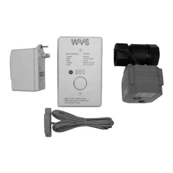
Water Valve Shutoff
Monitors flooding from
leaking or broken water
line
Automatic control of
main water supply line
Form C Relay output for
external monitoring
devices
Visual and audible
status indicators
Automatic self testing
Covers large area when
used with multiple
sensors
Low voltage design with
battery backup
WVS
Water Valve Shutoff
Advertisement
Table of Contents

Summary of Contents for GEORGE RISK INDUSTRIES WVS
- Page 1 Water Valve Shutoff Monitors flooding from leaking or broken water line Automatic control of main water supply line Form C Relay output for external monitoring devices Visual and audible status indicators Automatic self testing Covers large area when used with multiple sensors Low voltage design with battery backup ...
-
Page 2: Warranty
If the valve is open, a press and hold will cause the valve to close. If the valve is closed, a press and hold will open the valve. WARRANTY: One year warranty against workmanship, material and factory defects. TOLL-FREE 1-800-445-5218 • 1-800-523- GEORGE RISK INDUSTRIES, INC. 1227 G.R.I. PLAZA (308) 235-4645 KIMBALL, NE 69145 FAX (308) 235-3561 E-MAIL: grisales@megavision.com... -
Page 3: Specifications
Max. Wire Length to Sensors 200 ft. Max. Wire Length to Valve 50 ft. CONTACT YOUR G.R.I. DISTRIBUTOR OR CALL: TOLL-FREE 1-800-445-5218 GEORGE RISK INDUSTRIES, INC. TOLL-FREE 1-800-523-1227 G.R.I. PLAZA (308) 235-4645 KIMBALL, NE 69145 FAX (308) 235-3561 E-MAIL: grisales@megavision.com MADE IN U.S.A. - Page 4 IMPORTANT CONSIDERATIONS BEFORE YOU BEGIN: • DO NOT INSTALL THE GRI WVS SYSTEM ON SUPPLY LINES FOR FIRE SUPPRESSION SYSTEMS. • Installation of the GRI Water Valve Shutoff System requires a basic knowledge of plumbing as well as specialized tools for cutting pipe and joining fittings.
- Page 5 Depending on your plumbing system, you will need one or more pipe fittings to transition from your water pipe to the 1” female (NPT) threaded connection on the WVS Valve. It is recommended that unions be placed on both sides of WVS valve for easy removal.
-
Page 6: Step 5 - Remote Connections
The WVS can also be remotely signaled to close the valve, this is done by connecting a remote device to terminals #2 and #14. Closing the circuit between these terminals, places the controller into a lockout feature. When placed in this configuration the controller places the valve assembly into the fully closed position and will continually annunciate and indicate the closed condition. -
Page 7: Sensor Testing
Begin by applying 12VDC power to terminal #1. Immediately after power is applied to the controller initialization begins by first checking for the correct sensor control voltage at terminal #7, if correct, the controller then applies power to the WVS Valve and checks for proper valve voltage at terminal # 4, only if this is correct will it then start moving the valve to either the open or closed position. - Page 8 Valve Common Green Open Valve Open Closed Valve Close Green Sensor Control Sensor Cntr White Sensor Alarm Sensor Alrm Black Ground Sensor Grd 12VC Sensor Pwr Water Sensor Sensor Cat 5 2600WVS Cable Cable (Option) WVS Electrical Diagram Water Sensor 2600/2600T...
- Page 9 Note: 2600/2600T 2600/2600T Splice To Additional Sensors 12VDC Ground Sensor Alrm Controller 2600WVS Sensor Cntrl Sensor Diagram 1 2600/2600T 2600/2600T Power Supply 12VDC To Additional Sensors 12VDC Ground Sensor Alrm Controller 2600WVS Sensor Cntrl Sensor Diagram 2...
-
Page 10: Remote Diagram
Assembly 2600WVS Zone Aux Pwr Ext Cnt Relay Security Panel Remote Diagram TOLL-FREE 1-800-445-5218 • 1-800-523-1227 GEORGE RISK INDUSTRIES, INC. (308) 235-4645 • FAX (308) 235-3561 G.R.I. PLAZA E-MAIL: grisales@megavision.com KIMBALL, NE 69145 WEB SITE: www.grisk.com MADE IN U.S.A. 5/11/2009...
Need help?
Do you have a question about the WVS and is the answer not in the manual?
Questions and answers