
Summary of Contents for Go EBSRAY V Series
- Page 1 Publication # 1301-00 EBSRAY PUMPS INSTALLATION, OPERATION AND MAINTENANCE INSTRUCTIONS V Series Model V15...
-
Page 2: Table Of Contents
CONTENTS SECTION 1 - GENERAL..........................3 INTRODUCTION..........................3 1.1 CAUTION ............................ 3 1.2 WARNING........................... 3 1.3 TRANSPORTATION AND PACKING ..................... 3 1.4 INSPECTION ON RECEIPT - SHORTAGES ................... 3 1.5 HANDLING..........................3 SECTION 2 - INSTALLATION ........................3 2.1 LOCATION..........................3 2.2 FOUNDATIONS ........................... -
Page 3: Section 1 - General
SECTION 1 - GENERAL INTRODUCTION 1.3 TRANSPORTATION AND PACKING This publication is intended to assist those Standard domestic packing suitable involved with the installation, operation and shipment in covered transports. Ports must be maintenance of EBSRAY Model V15 Rotary Sliding sealed to exclude ingress of solids. - Page 4 the factory. To ensure this has been maintained during transit alignment MUST BE checked once before startup and again after the unit has been run under actual operating conditions. NOTE: The following procedures are typical only and reference should be made to data for specific coupling types.
-
Page 5: Section 3 - Operation
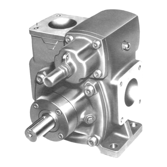
SECTION 3 – OPERATION 3.1 DESCRIPTION 3.2 LUBRICATION The Ebsray Model V15 is a positive displacement No 'in service' lubrication is required on EBSRAY sliding vane pump, primarily intended for the Model V15 pumps. transfer of low to medium viscosity liquids. The pump is of a multi-port design allowing for either 3.3 START-UP CHECKLIST 90 °... -
Page 6: Inspection
a suitable drift. 3. Remove 'O' ring from cover. Or, if fitted with mechanical seal: remove 4. Remove blanking cover or Valve cartridge. Stationary seal faces and 'O'rings from bearing housing/s then loosen grubscrews 5. Remove 'O' ring from blanking cover or Valve and remove rotating seal assemblies from cartridge. -
Page 7: Standard General Clearances
TABLE 1 STANDARD GENERAL CLEARANCES AND SIZES FOR TEMPERATURES O ° ° - 100 ° ° C Rotor to liner clearance measured radially at 12 o'clock position. 0.03 - 0.08 mm Total axial clearance - liner minus rotor length measured along axis. 0.08 - 0.15 mm Total vane clearance –... -
Page 8: Part 2-Bypass Valve
1. Insert liner half way into drive end of body 11. Fasten bearing housing in position using four ensuring correct orientation cap screws. (see 4.5) 12. Fit 'O' ring to inspection end bearing housing. 2. Using a suitable jig, stand rotor/shaft assembly with drive end up. -
Page 9: Section 5 - Instructions For Reversing Direction Of Rotation
Always lock adjusting screw cap after any 4. Fit valve blanking cover to body with "O"ring, adjustment is made. fasten with four cap screws. Refit pump coupling half 5. Fit adjusting screw with cap and fibre washer to cover. NOTE: DO NOT USE EXCESSIVE FORCE TO Note:The bypass valve will require setting FIT COUPLING AS THIS MAY DISTURB AXIAL when the pump is recommissioned. - Page 10 3. The cast "S" on the liner must be towards the 5. Reassemble the removed components taking inlet port and the cast "D" must be towards the care not to damage the 'O'rings or lip seals. discharge port. The complete drive end housing assembly should be fitted first, followed by the inspection 4.
-
Page 11: Section 6 - Trouble Shooting
SECTION 6 - TROUBLE SHOOTING 6.1 FAILURE TO DELIVER LIQUID 6. Bearings worn - inspect and replace as 1. Incorrect direction of rotation. required. 2. Inlet filter/strainer blocked or leaking air. 6.4 PUMP IS NOISY 1. Air leakage in inlet piping. 3. -
Page 12: Section 7 - Parts Designation
SECTION 7 - PARTS DESIGNATION EBSRAY MODEL: V15 Rotary Sliding Vane pumps. REFER TO DRAWING Nº: CMP024 and Notes below. Cat# Description Cat# Description Body Valve Spindle Liner Seal Washer 1 or 2 Rotor/Shaft assembly Mechanical Seal Assembly 1 or 2 Location pin - Liner/Bearing housing Stationary Face –... -
Page 14: Section 8 - Type 46 Inspection End Bearing
SECTION 8 – SLEEVE TYPE INSPECTION END BEARING The EBSRAY V15 type 46 pump is of identical b) Shrink fit a new bush ensuring that the construction to the types described in this lubrication grooves in the bush are in brochure with the exception of the inspection end alignment with the cast slots in the bearing bearing housing assembly.
Need help?
Do you have a question about the EBSRAY V Series and is the answer not in the manual?
Questions and answers