
Summary of Contents for Gelec DLLC7000
- Page 1 User’s & Technical Manual – DIFFERENTIAL LIQUID LEVEL CONTROLLER DLLC7000 DIFFERENTIAL LIQUID LEVEL CONTROLLER DLLC7000 INDUSTRIAL ELECTRONICS GELEC Industrial Electronics PAGE 1...
-
Page 2: Table Of Contents
PRECAUTIONS!..................................... 3 MANUFACTURER’S WARRANTY, GENERAL TERMS AND CONDITIONS ............... 4 DISPOSAL OF OLD ELECTRICAL & ELECTRONIC EQUIPMENT ..................5 DIFFERENTIAL LIQUID LEVEL CONTROLLER DLLC7000 ....................... 5 GENERAL DESCRIPTION ................................... 6 DLLC7000 VERSIONS ..................................7 DLLC7000 OVERVIEW & CONFIGURATION ..........................7 PNEUMATIC SECTION .................................. -
Page 3: Precautions
DIFFERENTIAL LIQUID LEVEL CONTROLLER DLLC7000 PRECAUTIONS! There are no serviceable parts inside the DLLC7000 unit. Not to be opened by any unauthorized person. All repairs to the device must be carried out by the manufacturer. Improper handling may result in serious personal injury and considerable material damage. -
Page 4: Manufacturer's Warranty, General Terms And Conditions
Any necessary replacement parts and necessary repair work are totally covered free of charge. All products are designed and produced by GELEC to be in compliance with the EU norms applying to them. GELEC is not responsible for direct or indirect damages or malfunction caused by improper use or installation of the DLLC7000. -
Page 5: Disposal Of Old Electrical & Electronic Equipment
In order to ensure the best performance and effective use of the DLLC7000, we recommend that you read the information in this manual carefully and follow the instructions contained. -
Page 6: General Description
DIFFERENTIAL LIQUID LEVEL CONTROLLER DLLC7000 GENERAL DESCRIPTION The DLLC7000 is a programmable, rangeable device used for liquid level control within a desirable region, in open tanks of height from 10cm up to 500cm, with analog sensor and digital output. Its operation is based on the measurement of liquid’s hydrostatic pressure. -
Page 7: Dllc7000 Versions
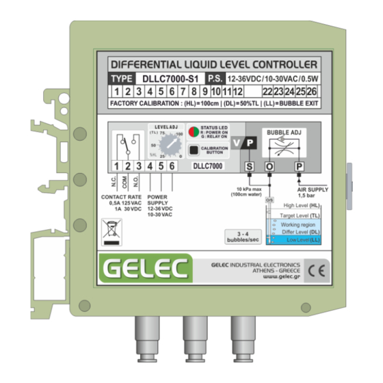
User’s & Technical Manual – DIFFERENTIAL LIQUID LEVEL CONTROLLER DLLC7000 DLLC7000 VERSIONS DLLC7000 VERSIONS DLLC7000 is provided in two versions with different pressure sensors, in order to meet a wide range of level measurement application needs. DLLC7000-S1 DLLC7000-S5 Operating pressure range 0-10 kPa (1.45 psi) - Page 8 User’s & Technical Manual – DIFFERENTIAL LIQUID LEVEL CONTROLLER DLLC7000 FUNCTION/CALIBRATION BUTTON The Function/Calibration button is used during calibration process and operating mode selection (FILLNG/DRAINING). Refer to the relevant sections in this manual for more information. ON-BOARD POTENTIOMETER (KNOB) The potentiometer’s position, adjusts the liquid’s Target level (TL) into the tank.
-
Page 9: Pneumatic Section
Temperature Compensated & Calibrated, this sensor is laser trimmed for precise Span, Offset calibration and temperature compensation. Having a gauge pressure sensor, the DLLC7000 uses the atmospheric pressure as a reference. This means that it must be installed in a vented electronic panel in order to have the same pressure conditions with the measured tank, which is open/vented by default. - Page 10 Don’t install the tube deeper than your DLLC7000 version allows. The excessive applied pressure can cause permanent damage or degradation to the device’s pressure sensor.
- Page 11 User’s & Technical Manual – DIFFERENTIAL LIQUID LEVEL CONTROLLER DLLC7000 CONNECTION TUBES The adaptors are suitable for 6/4mm tubes and the supported types are PA6, PA11, PA12, Polyurethane, Polyethylene, PTFE and FEP. Ensure that the tubes meet the operating requirements of your application (pressure, temperature, safety etc.).
-
Page 12: Installation
In the back side of DLLC7000, there is a clip for the mechanical mounting (lock) on an Ω- type mounting rail (DIN NS32/NS35), with the release hook at the bottom. The device should have at least 60mm free space below it for the air pipes and 15mm on top of it, for the wires. - Page 13 Re-calibrating Low Level will solve the issue, refer to the relevant section. DLLC7000 has a gauge pressure sensor which uses the atmospheric pressure as a reference. Therefore, the application tank must be open or vented and the measured fluid constantly under atmospheric pressure.
- Page 14 (1m of water in DLLC000-S1 / 5m of water in DLLC7000-S5), unless otherwise stated on the product label. So, the level which generates the maximum output signal corresponds to the maximum pressure that your version can handle.
-
Page 15: Electrical Section
DIFFERENTIAL LIQUID LEVEL CONTROLLER DLLC7000 10. ELECTRICAL SECTION ELECTRICAL CONNECTIONS The DLLC7000 housing is equipped with 6 connection terminals, two triple screw terminal blocks per side (top & bottom). The terminal blocks are manufactured to provide resistance to stress corrosion cracking, electrolytic corrosion, rusting and screw loosening in case of vibrations. - Page 16 E.g. for R =450KΩ the device provides V = 4,5V. PRIOR CONTACT WITH GELEC IS NECESSARY FOR PWM OUTPUT FEATURE TO BE INCLUDED DLLC7000 Connection Diagram GELEC Industrial Electronics PAGE 16...
-
Page 17: Operating Philosophy - Level Description
User’s & Technical Manual – DIFFERENTIAL LIQUID LEVEL CONTROLLER DLLC7000 OPERATING PHILOSOPHY – LEVEL DESCRIPTION The DLLC7000 operating philosophy is based on a desirable working region and four critical liquid levels, which can be calibrated from the user to meet the application requirements. - Page 18 User’s & Technical Manual – DIFFERENTIAL LIQUID LEVEL CONTROLLER DLLC7000 The user can program the (DL) at a desirable level following the calibration process, without changing the other two le vel values. The Differential Level (DL) you select each time, is stored in the unit’s memory as a percentage of (HL).
- Page 19 Notice that according to the described example’s steps, for every (TL) you select with the potentiometer, the (DL) will be 12,5% less. PRESELECTED VALUES The standard version DLLC7000-S1 can control the liquid level in tanks with height from 10cm to 100cm and has the below preselected values and parameters. ...
-
Page 20: Level Calibration Process
User’s & Technical Manual – DIFFERENTIAL LIQUID LEVEL CONTROLLER DLLC7000 12. LEVEL CALIBRATION PROCESS With this process, you can calibrate the device to store the required parameters, in order to function according to your application needs. Follow the appropriate steps for each level calibration. -
Page 21: Filling / Draining Operating Modes
13. FILLING / DRAINING OPERATING MODES DLLC7000 has two programmable operating modes for liquid level control, FILLING MODE and DRAINING MODE. The user determines whether the level control is done through filling or draining mode. - Page 22 (DL). OPERATING MODE SELECTION (F/D) You can see the mode that the DLLC7000 unit operates by the flashing colour of the LED just after the device power supply. According to the pre-programmed operating mode, the led flashes for three seconds with the corresponding color.
-
Page 23: Dimensions
User’s & Technical Manual – DIFFERENTIAL LIQUID LEVEL CONTROLLER DLLC7000 NOTE When power is interrupted and the liquid level is between the (TL) and the (DL), the relay will be de-activated. After the power is restored, if the device is operating in filling mode, the relay will be activated and the tank will fill up to the (TL). -
Page 24: Technical Specifications
User’s & Technical Manual – DIFFERENTIAL LIQUID LEVEL CONTROLLER DLLC7000 15. TECHNICAL SPECIFICATIONS DLLC7000 GENERAL DATA Unit dimensions (HxWxD) 95 x 25 x 85 mm Minimum installation area (HxWxD) 170 x 26 x 86 mm Weight 145 gr Housing material Polyamide (PA 6.6) - Green... - Page 25 User’s & Technical Manual – DIFFERENTIAL LIQUID LEVEL CONTROLLER DLLC7000 Relay contact characteristics Resistance (initial) Maximum 50 mΩ at 1A 6 VDC Rating (resistive) 0.5A 125 VAC or 1A 30 VDC Max carrying current Max switching power 62.5 AV, 30 W...
- Page 26 User’s & Technical Manual – DIFFERENTIAL LIQUID LEVEL CONTROLLER DLLC7000 INDUSTRIAL ELECTRONICS 4 Kikladon Str. Maroussi, Athens – Greece, GR-15125 Telephone: +30 210 6144074 - Fax: +30 210 6144074 - info@gelec.gr GELEC Industrial Electronics PAGE 26...
Need help?
Do you have a question about the DLLC7000 and is the answer not in the manual?
Questions and answers