
Summary of Contents for Vidalux HY-845 Series
- Page 1 INSTALLATION AND OPERATING MANUAL HY-845 Range INSTALLERS PLEASE NOTE, THESE INSTRUCTIONS ARE TO BE LEFT WITH THE CUSTOMER Technical Support: 01524 489939 Warranty Claims Or Delivery Damage: www.vidalux.co.uk...
- Page 2 VIDALUX CLEAR & BRIGHT WATER SOFTENER Guaranteed to get rid of limescale Live in a hard water area?? Limescale in the kettle and on bathroom fixtures?? Suffering from unknown adverse health effects from this polluted drinking water?? If you have a steam shower and the generater becomes blocked with limescale and stops working...
- Page 3 Thank you for purchasing this product. To guarantee the product delivers a long service life, please ensure it is fi tted and used in accordance with the instructions contained in this booklet. Please check that the boxes contain all the items listed below, and report to us any parts that are missing or damaged prior to assembly and within 48 hours of receipt.
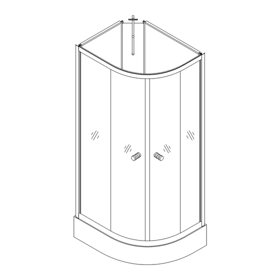
- Page 4 HY-845 Shower Contents Below is a list of the parts you should have received for the installation of your shower. Please note that several parts may be pre-fi tted in place, such as the monsoon shower head, etc. Please note, the design and shape of parts may change occasionally but will always off er the same or greater functionality.
- Page 5 Tray/Base with Waste assembly and fl exible waste pipe pre-fi tted (shape and size vary according to model). Two Curved polished Aluminium frame sections. Thermostatic shower valve Chrome monsoon arm, Monsoon head, swivel joint and two nuts for fixing. Glass shelf and fi ttings. Two longer and two slightly shorter Flapped seals and a pair of Magnetic door seals.
-
Page 6: Important Notice
IMPORTANT NOTICE Before you proceed with fi tting your Vidalux Shower please read and understand the following: By commencing testing and installation of the unit you are agreeing to the Terms and Conditions set out by us: copies of which are available by contacting us by by email or by telephone (details on the cover of this manual). -
Page 7: Before You Begin
Before you begin Assembly requires two persons. Tools needed to assemble this shower cabin: Electric screwdriver with a selection of heads, regular screwdrivers, pipe grips, spanners, spirit level, sharp knife and rubber mallet. Connection of the electrical supply and plumbing may require additional tools. Do not fully tighten any screw fixings initially during build as this allows the frame to move a little and aid location of all holes and screws;... - Page 8 Assembly Do not fi t the shower into locations where you do not have at least 40cm access all around the cabin both for installation and for future service access. We advise you do not fi t sinks, toilets etc that restrict access behind the shower.
- Page 9 FITTING SEAT (OPTIONAL) If your product came with a seat you may choose to install this item. Before commencing full assembly of the product you will need to prepare and fi t the seat. You need to drill three holes for the fi xing bolts into the tower at your preferred height.
- Page 10 LEVELING AND FITTING THE TRAY Remove the protective fi lm covering the base. Connect the soil pipe, trap and any couplings to the fl exible waste under the tub. You may choose to fi t either a HEPV0 trap with the appropriate couplings or choose to fi t a McAlpine ST28M coupling to a McAlpine 28-NRV trap.
-
Page 11: Front Frame
FRONT FRAME Locate the two silver coloured upright frame sections and the two curved frame rail sections. You will need the 8 x LONGEST screws to join these sections together. The inside facing edges of the rails will be tapered, DO NOT FULLY TIGHTEN THE SCREWS - while the flat edge will meet the tray and the other will be closest to the bathroom ceiling. -
Page 12: Rear Panel Assembly
REAR PANEL ASSEMBLY Site the front framework on to the tray. Next taking each panel in turn, lifting slightly off from the tray, twist the rear panels into place, fixing to the front framework. Once in position, set the panel down NOTE: A large bead of sealant MUST be run between the back panels and Front Frame work to provide an extra level of water protection. - Page 13 DO NOT SCREW THE PANELS TO THE BASE JUST YET FIXING THE BACK PANELS TO THE TRAY The rear glass panels can now be fi xed to the tray. Wipe away any excess sealant one completed At the rear of the shower the lip of the frame has fi xing holes to enable the screws provided to be used to fasten the rear glass panels to the tray.
- Page 14 INSTALLING THE FIXED SIDE GLASS PANELS Locate the two fi xed glass panels. These are diff erent from the doors as they do NOT have any holes pre-drilled. Now position this glass panel up to the frame pushing the long edge of the glass into the upright of the frame until FULLY bedded into the frame upright.
- Page 15 GLASS RETAINING CLIPS Next you need to fi t the Retaining Clips to hold the glass fi rmly. Position a clip tight up to the glass on the inside of the upper and lower rails, mark the position and drill a small hole then fi x a screw to hold the clip in place.
- Page 16 (image based on top cam fi tting) To fi t each of the cams, fi rst select the appropriate cam for the position on the door: 4 x Push button/Quick release for the lower position on the doors. 4 x Standard non push button for the upper position on doors. Position the Cam Body on the outside facing side of the door (curve pointing outwards).
-
Page 17: Fitting The Door Handles
FITTING THE DOOR HANDLES Each of the two shower doors requires a pair of chrome fi nished door handles to be fi tted. Each handle is comprised of several parts. Position the main handle part on the outside of a door ensuring the Chrome Washer and a Clear Washer are positioned also on the outside face over the thread. - Page 18 HAND SHOWER AND RISER You are now ready to assemble and connect the hand shower. The hand shower comprises of: Multi function hand shower Chrome fi nished riser bar Hand shower holster Chrome water hose Rear retaining nut Fitting screw The lower part of the riser bar has a threaded water connection.
- Page 19 GLASS SHELF Assemble the shelf fully before fi tting into the shower. Position the lower chrome rail over the holes in the glass on the underside of the shelf with the silver grommets positioned between the two. On the upper side of the glass, pass the bolt through a washer and through the hole in the glass and fasten into the end of the lower rail.
-
Page 20: Shower Valve
SHOWER VALVE The shower valve can be accessed from the rear of the shower and is located on the central tower. The valve is divided into three parts that are joined together. The uppermost part is the divertor. There are three connections able to be made here. - Page 21 SHOWER SEALS This shower comes with 4 fl apped shower seals that are in two diff erent lengths. SHORT FLAPPED The shorter fl apped seals fi t onto the end of the fi xed glass panels. LONG FLAPPED The longer fl apped seals fi t onto the trailing edges of the doors.
-
Page 22: Water Connections
Water Connections This product requires a hot and cold water supply. Your Hot and Cold water supply pipes should ideally be fi nished about 1 meter above the fl oor centrally in the corner and fi nished with 15mm compression isolating valvea. -
Page 23: Water Testing
Sealing the Shower OPTIONAL: Under normal use, the shower will return all water back into the tray. Should you choose, we recommend that you seal the shower internally with a good quality bathroom sealant to provide an extra level of water proofi ng. -
Page 24: Final Testing
Final Testing Check and test that each outlet function (hand shower, body jets and monsoon) work as expected by rotating the DIVERTOR DIAL (top chrome dial). Check the ON/OFF dial enables the water to be fully on or off in the position indicated on the valve markings. -
Page 25: Valve Operation
Valve Operation There are 3 control dials inside your Shower Cabin. These dials control the output functions, water fl ow and temperature of your shower. The top dial can be turned to allow you to choose which output you wish to use: Body Jets, Overhead (Monsoon) Shower and Hand Shower. - Page 26 Cleaning and third party product use DO NOT CLEAN BY SPRAYING THE HAND SHOWER DIRECTLY INTO AREAS THAT MAY PASS WATER - UNLESS YOU HAVE ADDED THE ADDITIONAL INTERNAL SILICONE IN PREVIOUS STEP This shower should be cleaned after every use to remove the build up of dirt and bacteria. We would recommend that after normal showering use, that the cabin doors are left open until the inside is fully dry.
- Page 27 Thermostatic Cartridge Your shower is fi tted with a Thermostatic Cartridge. Should you need to remove or replace the cartridge for maintenance or replacement, follow the instructions below. Q: I am having to turn the dial round as far as it will go to the hottest setting and the water is only just warm.
- Page 28 With the Chrome dial removed you will see a plastic ring covering with the Thermostat underneath. Note down the position the ring is placed in. Pull the plastic ring (Temperature safety lock) towards you to remove. Keep this part safe You will now see the head of the Thermostat clearly visible.
-
Page 29: For Technical Assistance
FOR TECHNICAL ASSISTANCE PLEASE CALL 01524 489939... - Page 30 This form must be filled out by the plumber/installer and electrician (where applicable) in order to validate the warranty. You are required to register the warranty online at www.vidalux.co.uk You MUST register the product warranty within 90 days following delivery...
Need help?
Do you have a question about the HY-845 Series and is the answer not in the manual?
Questions and answers