
Related Manuals for nxt BIA-nXt-Protect 1-22

Summary of Contents for nxt BIA-nXt-Protect 1-22
- Page 1 Restart Pump Controller Single Pump Protection and Control Module BIA-nXt-Protect 1-22 PN 811202 Installation and Operation Manual BIA-nXt-PROTECT1 Instruction Manual...
-
Page 2: Shortcuts
PRESS and HOLD the In manual mode AUTO/MANUAL button, for PRESS and HOLD the 5 seconds At any time press the STORE/SET button START/STOP button for 3 seconds to mute the alarm. It will now beep every 5 minutes BIA-nXt-PROTECT1 Instruction Manual... - Page 3 AUTO/MANUAL decreases a value In manual mode, with no Press STORE/SET to proceed pump running, press the through the parameter menu STORE/SET button for 5 sec. Long press STORE/SET to store all changes and exit BIA-nXt-PROTECT1 Instruction Manual...
-
Page 4: Introduction
The controller is easy to set up with an initial push button calibration and individual parameters can be fine-tuned. A nXt-Protect controller is particularly useful where there is the need to control and protect pump installations managing the automatic operation through a variety of switching methods without the need to create a bespoke control solution. -
Page 5: Table Of Contents
17. Warranties – Terms and Conditions ............20 ISO 7010 Symbols used in this manual Warning - Electrical safety Warning – Potential consequences of use outside of intended application(s). Includes environmental condition warnings. Mandatory warning Warning to disconnect power Read carefully BIA-nXt-PROTECT1 Instruction Manual... -
Page 6: Modes Of Operation
Default line. Supports run / no run level protection at the source. Mode Sensorless time control When first powered on the nXt-Protect will display the current dipswitch operating mode (binary code), the hardware and the software version. BIA-nXt-PROTECT1 Instruction Manual... -
Page 7: Technical Specifications
5 min default Alarms Audible alarm and flashing screen To avoid ‘nuisance’ alarming, many of the default protection parameters have values with a wide tolerance. The installer is encouraged to optimise the settings to achieve optimum results BIA-nXt-PROTECT1 Instruction Manual... -
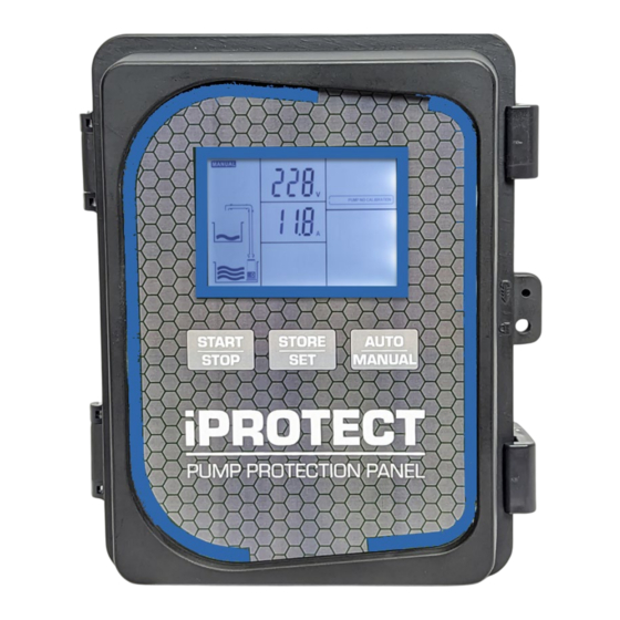
Page 8: Display
Display The nXt-Protect display provides a real time indication of the operational mode and the current state of the controller, including real-time voltage/current and any error messages. Only the icons relevant to the selected operational mode will display. Error Controller... - Page 9 Display con’t The nXt-Protect controller operates according to pre-programmed logic applied to each ‘mode’. Changing the Dip Switches inside the controller then cycling the power will activate the selected logic mode. Examples of common applications are detailed later in this manual but with an understanding of how the controller responds to various inputs in each of the modes the controller can be used for application other than what is suggested.
-
Page 10: Electrical Connections
If in doubt online resources exist i.e. Cable Size Calculator AS/NZS 3008 or seek advice from an electrical engineer or other suitably qualified person(s) Note that nXt-Protect is intended to control a standalone single pump only. If the installation must connect to a BMS or must operate an external alarm, enquire about... -
Page 11: Parameter Calibration
When the display shows 099, release the START/STOP button. Grinder / Macerating Pumps Manually programming the nXt-Protect around the pump nameplate Full Load Current allows the pump to generate maximum torque. This may be a preferred alternative to calibration around the ‘normal’ hydraulic loading current value in situations with heavily contaminated liquids. -
Page 12: Program Parameters
Button Lock – set to 01 to activate Manual/Auto and Store buttons to unlock Open Phase Protection When using the nXt SPC in conjunction with a VFD set to OFF Pump start delay time: range 0 – 254 sec Pump stop delay time: range 0 –... - Page 13 For example, the controller can be connected in series with a VFD controlled pump to provide additional control inputs or to utilise the nXt-Protect controller delay times. For even greatly flexibility in your installation the nXt-Protect controller can be used as a ‘module’ in a more complex control environment.
-
Page 14: Quick Guide: Transfer - Source/Destination Control
In situations where the destination is a significant distance from the source it is possible to control by fitting a normally-open pressure switch to the delivery line OR to use a remote wireless sensor to trigger a switched input. Connect across #4 and #5 BIA-nXt-PROTECT1 Instruction Manual... -
Page 15: Quick Guide: Drainage Mode, Float Connected To Pump
The Controller provides additional protections excluding dry run protection. A float connected to the controller can provide high level alarm function Parameter 001 must remain set to 0.0A to prevent underload alarming when the pump float interrupts pumping operation BIA-nXt-PROTECT1 Instruction Manual... -
Page 16: Quick Guide: Drainage Mode, Floats Connected To Control
The alarm will turn off when the Hi Level alarm switch 4/6 in in its Off (Down) position. The pump will continue to run until the Pump Stop switch 1/3 is in the Off (down) position See page 13 for wiring twin control floats to achieve greater switching differential BIA-nXt-PROTECT1 Instruction Manual... -
Page 17: Quick Guide: Pressure Boosting - Switched Input
PCB and cycle the power Pump On/Off operation is controlled via a pressure switch on the delivery line. Additional (optional) run/no run protection can be fitted at the source Or employ probes at the source BIA-nXt-PROTECT1 Instruction Manual... -
Page 18: Quick Guide: Sensorless Time Control
011 has passed. Pump stop timer (manual mode): range 0 – 254 min 0 min In Manual operation mode the pump can be set running and it will stop after the time set in parameter. BIA-nXt-PROTECT1 Instruction Manual... -
Page 19: Fault Messages
OPEN PHASE The power supply has lost power. Check fuses and wiring. PUMP NO Check the calibration. Calibration not complete CALIBRATION Pump draw must exceed 1 amp BIA-nXt-PROTECT1 Instruction Manual... -
Page 20: Warranties - Terms And Conditions
New Zealand. 8) Our warranty commences from the date of purchase of the above- mentioned pumps. Proof of purchase is required before consideration under warranty is given. Record your date of purchase in the space below and retain this copy for your records. Date of Purchase ..........Model Purchased ..........BIA-nXt-PROTECT1 Instruction Manual... - Page 21 For any queries regarding use of the contained information please feel free to contact White International Pty Ltd. BIA-nXt-PROTECT1 Instruction Manual...
Need help?
Do you have a question about the BIA-nXt-Protect 1-22 and is the answer not in the manual?
Questions and answers
Can my float switch be 50m away from controller
The documents do not specify a maximum distance for the float switch from the controller. However, they mention that the installing technician must ensure the cable cross-section meets AS/NZS 3008 requirements, considering cable length, type, and current draw. Therefore, a float switch can be located 50 meters away if the correct cable size is used according to these standards.
This answer is automatically generated