Table of Contents
Advertisement
Quick Links
Advertisement
Table of Contents

Summary of Contents for Adamczewski AD-MM 400 FE
- Page 1 Digital Indicator AD-MM 400 FE Manual Revision 1.2 / 2021-05-18...
-
Page 2: Table Of Contents
6.1.2 AD-MM 400 FE as Modbus slave ....16 6.2 Parameters ....... . 17 6.2.1... - Page 3 7 Modbus 7.1 RS-485 interface parameter ..... . . 24 7.2 Changing the slave address ..... . . 24 7.3 Data format .
-
Page 4: About This Manual
1 About this manual This manual is part of the product. Read the operating instructions thoroughly before using the unit. Keep the operating manual for the entire life of the product and keep it ready for reference. Pass the manual to each subsequent owner or user of the product. 1.1 Structure of warnings WARNING Warning Note... -
Page 5: Security
The AD-MM 400 FE is intended for connection to an RS-485 interface on the other devices are connected. The AD-MM 400 FE can be connected to a PC or laptop via the configuration interface. The AD-MM 400 FE is intended for installation in front panels of control cabinets. -
Page 6: Qualification Of Personnel
Operate this product only in perfect condition, taking into account the operating instructions, the usual regulations and guidelines as well as the applicable safety regu- lations and accident prevention regulations. Extreme environmental conditions affect the function of the product. Protect product from impact Use only in indoor areas Protect product from moisture 2.4 Qualification of personnel... -
Page 7: Product Description
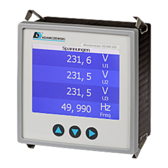
3 Product Description The monitor module AD-MM 400 FE is a display and control unit for the front door installation. It can be connected to other devices of the Adamczewski elektronische Messtechnik GmbH or to devices from other manufacturers via its RS-485 interface. -
Page 8: Ordering Code
AD-PC Figure 3.1: Blockdiagram of the AD-MM 400 FE 3.5 Display and Controls The AD-MM 400 FE has a color TFT display for displaying the data and three buttons for operation and configuration. Short and long keystrokes are evaluated differently. - Page 9 TFT-Display Down Figure 3.2: Display and control elements of the AD-MM 400 AD-MM 400 FE Function of the keys. Multiple functions are separated by ’;’. Key ’Up’ Scroll up; increment number Key ’Up’, long Switch from manual to autoscroll display mode Key ’Down’...
-
Page 10: Specifications
4 Specifications 4.1 RS-485 interface The connection to the other devices must be established via a twisted shielded bus cable. The order of the devices among each other is arbitrary. For reasons of electro- magnetic compatibility, the shield must be connected at both ends to a large area and to be connected in a good conducting manner to the protective end. -
Page 11: Case
4.3 Case Description Value Unit Enclosure Type Enclosure Housing to IEC 61554 Housing Size HxWxD 96 x 96 x 44 Panel Cutout HxB 92 (+0.8) x 92 (+0.8) Protection class IP20 Terminal technology screw terminals, pluggable Cross-section fine- stranded , solid Weight 4.4 Ambient Conditions Description... -
Page 12: Galvanic Isolation, Test Voltages
4.6 Galvanic Isolation, Test Voltages Description Value Unit Auxiliary Voltage to RS-485 kV, 1 min. -
Page 13: Assembly And Commissioning
5 Assembly and Commissioning 5.1 Electrical Connection DANGER Life hazard due to electric shock The terminals of the auxiliary voltage inputs are hazardous to contact. Disconnect mains voltage and secure against restarting. Ensure contact protection of the connections. Protect all connections from electrostatic discharge. 5.2 Commissioning the device Disconnect the power supply. -
Page 14: Configuration
6 Configuration The information in this chapter refers to the configuration of the AD-MM 400 FE with the Configuration Software AD-Studio via the configuration interface. 6.1 Operating modes The AD-MM 400 FE can be either a Modbus master (default setting) or a Modbus slave. - Page 15 2. The Modbus data tables of the connected slaves must be known. 3. Set the desired slave address on all slaves. 4. Make sure that all slaves and the AD-MM 400 FE use the same baud rate and parity. When using devices of the Adamczewski elektronische Messtechnik GmbH , you do not have to worry about it because all devices use the same settings (19200 baud, 8 data bits, even parity, 1 stop bit).
-
Page 16: Ad-Mm 400 Fe As Modbus Slave
6.1.2 AD-MM 400 FE as Modbus slave In this operating mode, the AD-MM 400 FE receives the values to be displayed from an external Modbus master, e.g. A PLC or a PC. The configuration of the displays is... -
Page 17: Parameters
4. The configuration of the display lines and displays is exactly the same as in the master operating mode. 5. The AD-MM 400 FE now behaves like any other Modbus slave. Modbus function 16 (Write Multiple Registers) can now write data to the configured registers. -
Page 18: Views
6.2.1 Views The AD-MM 400 FE can display up to 10 Views. These can be scrolled automatically with the ’up’ and ’down’ buttons either manually or with a timer. Anzeige 1 down Anzeige ... down Anzeige 10 down Figure 6.5: scroll through the views A view contains a title line and can contain one to four lines of data. - Page 19 Titelzeile Anzeigezeile1 Figure 6.6: single-line displaylayout Titelzeile Anzeigezeile1 Anzeigezeile2 Figure 6.7: two-line displaylayout...
- Page 20 Titelzeile Anzeigezeile1 Anzeigezeile2 Anzeigezeile3 Figure 6.8: three-line displaylayout Titelzeile Anzeigezeile1 Anzeigezeile2 Anzeigezeile3 Anzeigezeile4 Figure 6.9: four-line displaylayout...
-
Page 21: Display Lines
The following parameters are available to configure the displays. INFO Default values of the AD-MM 400 FE The AD-MM 400 FE contains as default values exemplary set- tings with which the data of the AD-LU 30 GT can be displayed as slave. -
Page 22: Device Functions
As a master, the AD-MM 400 FE automatically fetches the value from a holding register of the slave. In the slave mode, the values transferred by the master are displayed here. unit The physical unit of the value is displayed in this area. - Page 23 Master/Slave mode can be used to determine whether the AD-MM 400 FE is acting as master or slave on Modbus. With ’RS-485 slave address’, the slave address of the AD-MM 400 FE can be deter- mined in slave mode. In the master mode, this parameter has no meaning.
-
Page 24: Modbus
Adamczewski elektronische Messtechnik GmbH . 7.2 Changing the slave address If the AD-MM 400 FE is operating in slave mode, the slave address can be changed with the Configuration Software AD-Studio . The slave address is not relevant as a Modbus master. -
Page 25: Supported Functions
7.5 Supported Functions The AD-MM 400 FE supports the following functions as master and slave on the RS-485 interface. 3 (0x03) Read Holding Registers. 16 (0x10) Write Multiple Registers. 7.5.1 Read Holding Registers This function is used to read one or more registers. -
Page 26: Exception Codes
7.6 7.6 Exception Codes In the event of an error, the AD-MM 400 FE will respond with a Error telegram and one of the following exception codes. As The function code is returned with 0x80. 1 (0x01) The Modbus function is not supported. -
Page 27: Wiring Diagrams
8 Wiring diagrams 8.1 RS-485 The figure shows the configuration of the RS-485 interface with several nodes in a Modbus segment according to the specification ’Modbus over serial line’. Figure 8.1: RS-485 with several subscribers ITr A twisted, shielded cable must be used as a bus cable IDv Passive spur lines must be as short as possible Masse The ground connection of all bus nodes must be connected to each other and connected to the end of the bus, if possible at the bus master... -
Page 28: Terminal Assignment
M1, 1 RS-485 A M1, 2 RS-485 B M1, 3 RS-485 Masse M4, 1 Power supply AC1, DC- M4, 2 Power supply AC2, DC+ 3mm jack for VarioPass Figure 8.2: Terminal assignment of AD-MM 400 FE . View from back. -
Page 29: Appendix
9 Appendix 9.1 Maintenance During proper operation of the AD-MM 400 FE , this is maintenance-free. The device may only be repaired by the manufacturer in case of damage. 9.2 Malfunction If an error or a fault occurs, try to find the cause first. If the error persists, please contact the manufacturer or dealer of the device, which can be found in chapter 9.4.
Need help?
Do you have a question about the AD-MM 400 FE and is the answer not in the manual?
Questions and answers