Table of Contents
Advertisement
Quick Links
For more information, visit www.desatech.com
For more information, visit www.desatech.com
PROPANE/LP GAS "TUDOR" MODEL (V)T32P
WARNING: If the information in this manual is not fol-
lowed exactly, a fire or explosion may result causing
property damage, personal injury, or loss of life.
Do not store or use gasoline or other flammable vapors
and liquids in the vicinity of this or any other appliance.
WHAT TO DO IF YOU SMELL GAS
• Do not try to light any appliance.
• Do not touch any electrical switch
• Do not use any phone in your building.
• Immediately call your gas supplier from a neighbor's
phone. Follow the gas supplier's instructions.
• If you cannot reach your gas supplier, call the fire
department.
This appliance may be installed in an aftermarket*, permanently located, manufactured
(mobile) home, where not prohibited by state or local codes.
This appliance is only for use with the type of gas indicated on the rating plate. This appliance
is not convertible for use with other gases, unless a certified kit is used.
*Aftermarket: Completion of sale, not for purpose of resale, from the manufacturer.
NATURAL GAS
"TUDOR" MODEL (V)T32N, CHDV32NR
FOR YOUR SAFETY
FOR YOUR SAFETY
Save this manual for future reference.
Save this manual for future reference.
DIRECT-VENT FIREPLACE
OWNER'S OPERATION AND
INSTALLATION MANUAL
WARNING: Improper installation,
adjustment, alteration, service,
or maintenance can cause injury
or property damage. Refer to this
manual for correct installation
and operational procedures. For
assistance or additional infor-
mation consult a qualified in-
staller, service agency, or the
gas supplier.
Installation and service must be
performed by a qualified
installer, service agency, or the
gas supplier.
Advertisement
Table of Contents

Related Manuals for Desa TUDOR


Summary of Contents for Desa TUDOR
- Page 1 For more information, visit www.desatech.com For more information, visit www.desatech.com NATURAL GAS “TUDOR” MODEL (V)T32N, CHDV32NR PROPANE/LP GAS “TUDOR” MODEL (V)T32P WARNING: If the information in this manual is not fol- WARNING: Improper installation, lowed exactly, a fire or explosion may result causing adjustment, alteration, service, property damage, personal injury, or loss of life.
-
Page 2: Table Of Contents
TABLE OF CONTENTS SAFETY INFORMATION TABLE OF CONTENTS SAFETY INFORMATION ............2 CLEANING AND MAINTENANCE ..........28 PRODUCT IDENTIFICATION ............. 3 TROUBLESHOOTING .............. 29 LOCAL CODES ................3 ILLUSTRATED PARTS BREAKDOWN AND PARTS LIST ..32 PRODUCT FEATURES .............. 4 REPLACEMENT PARTS ............ -
Page 3: Product Identification
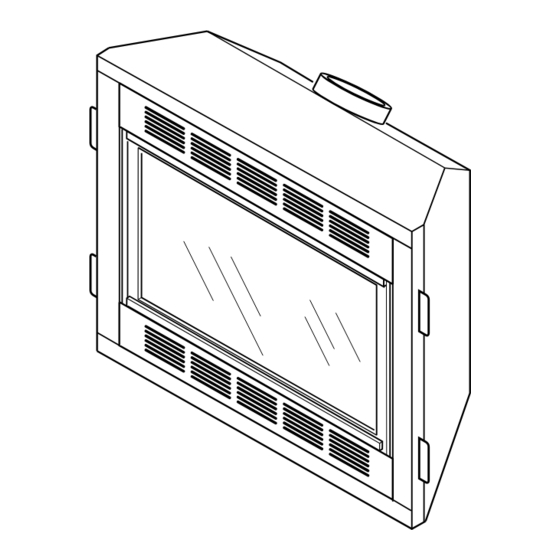
(Optional Installation) (Optional Installation) 12. Do not use this fireplace to cook food or burn paper or other Figure 1 - Tudor Direct-Vent Fireplace with Millivolt Ignition objects. 13. Do not use any solid fuels (wood, coal, paper, cardboard, etc.) LOCAL CODES in this fireplace. -
Page 4: Product Features
LOCATION AND SPACE REQUIREMENTS Flush with a wall Determine the safest and most efficient location for your DESA direct-vent fireplace. Make sure that rafters and wall studs are not in the way of the venting system. Choose a location where the heat... - Page 5 PRE-INSTALLATION PREPARATION Clearances Framing and Finishing PRE-INSTALLATION PREPARATION Continued CLEARANCES Minimum clearances to combustibles for the fireplace are as follows: " " " Back, and sides 0"/mm Perpendicular walls 6" (152mm) " Floor 0"/mm Ceiling to louver opening 42" (1067mm) Front 36"...
-
Page 6: Location Of Termination Cap
LOCATION OF TERMINATION CAP LOCATION OF TERMINATION CAP Fixed Openable Fixed Closed Closed Openable TERMINATION CAP GAS METER RESTRICTED AREA AIR SUPPLY INLET (TERMINATION PROHIBITED) A = clearance above grade, veranda, porch, deck, or balcony I = clearance to service regulator vent outlet [*72 inches (182.9cm) [*12 inches (30.5mc) minimum] minimum] B = clearance to window or door that may be opened... -
Page 7: Venting Installation Instructions
• Wear gloves and safety glasses for protection • Use extreme caution when using ladders or when on roof tops These models are tested and approved for use with DESA (direct- • Be aware of electrical wiring locations in walls and ceilings vent) pipe components and terminations. - Page 8 VENTING INSTALLATION INSTRUCTIONS Installation Planning VENTING INSTALLATION INSTRUCTIONS Continued 2. Direct vent pipe sections and components are designed with special twist-lock connections. Twist-Lock Procedure: The female ends of the pipes have lock- Female ing lugs (indentations). These lugs will slide straight into match- Locking Lugs ing slots on the male ends of adjacent pipes.
- Page 9 VENTING INSTALLATION INSTRUCTIONS Installation Planning (Cont.) VENTING INSTALLATION INSTRUCTIONS Continued For vinyl siding, stucco, or wood Combustible Exterior Wall: exteriors, a siding standoff must be installed between the vent cap and exterior wall. The siding standoff prevents excessive Cut Siding Away heat from damaging the siding materials.
- Page 10 VENTING INSTALLATION INSTRUCTIONS Installation Planning (Cont.) VENTING INSTALLATION INSTRUCTIONS Continued WARNING: Never run vent downward as this may cause excessive temperatures which could cause a Minimum Pipe fire. Operation of improperly installed and main- Siding Standoff Overlap 1 " tained venting system could result in serious injury, property damage or loss of life.
- Page 11 VENTING INSTALLATION INSTRUCTIONS Installation Planning (Cont.) VENTING INSTALLATION INSTRUCTIONS Continued Required Vertical (V) Vertical Pipe Horizontal (H) CORNER AND ALTERNATE INSTALLATION " min. None 30" max. " min. 1 ft. 48" max. Recommended Applications: " min. 2 ft. 60" max. •...
- Page 12 VENTING INSTALLATION INSTRUCTIONS Installation Planning (Cont.) VENTING INSTALLATION INSTRUCTIONS Continued HORIZONTAL SYSTEM INSTALLATION USING TWO 90° ELBOWS The following configurations show the minimum vertical rise requirements for a horizontal system using two 90° elbows. Venting with Two 90° Elbows Horizontal (H Vertical (V) Horizontal (H Horizontal (H...
- Page 13 VENTING INSTALLATION INSTRUCTIONS Installation for Vertical Termination VENTING INSTALLATION INSTRUCTIONS Continued INSTALLATION FOR VERTICAL TERMINATION 2. Assemble the desired lengths of pipe and elbows necessary to reach from the fireplace flue up through the firestop. Be sure Note: Vertical restrictor must be installed in all vertical installations. all pipe and elbow connections are fully twist-locked (see Fig- 1.
- Page 14 VENTING INSTALLATION INSTRUCTIONS Installation for Vertical Termination (Cont.) VENTING INSTALLATION INSTRUCTIONS Continued Vertical Termination Configurations Venting with One 90° Elbow Vertical (V) Horizontal (H) Figures 21 through 24 show four different configurations for verti- cal termination. 5' min. 2' max. 6' min.
- Page 15 INSTRUCTIONS Continued HIGH ALTITUDE INSTALLATION Your DESA direct-vent fireplace has been CSA tested and ap- proved for elevations from 0-2000 feet (USA) and elevations from 0-4500 feet (Canada) . When installing this fireplace at an elevation above 2000 feet (in the USA), you may need to decrease the input rating by changing the existing burner orifice to a smaller size.
-
Page 16: Fireplace Installation
VENTING INSTALLATION INSTRUCTIONS Continued PARTS LISTS FOR VENTING KITS AND DESA Venting Accessories COMPONENTS Number Description DESA Pipe & Vent Kits SC-47 Storm Collar - Galvanized Number Description WF-47 Wall Firestop - Galvanized RF-47-6 Roof Flashing - 0 to 6/12 Pitch - Galvanized P47-6 6"... - Page 17 FIREPLACE INSTALLATION Installing Optional Blower Accessories (Cont.) FIREPLACE INSTALLATION Continued 3. Place the blower against the lower rear wall of the firebox outer Switch Speed Control Bracket wrapper with the exhaust port directed upward. The blower Blower will fit inside the back opening and be held in position against Plug-In the back wall by the magnets (see Figure 25).
- Page 18 FIREPLACE INSTALLATION Installing Optional Blower Accessories (Cont.) FIREPLACE INSTALLATION Continued 3. Place the blower against the lower rear wall of the firebox outer White Wire Power Cord wrapper with the exhaust port directed upward and the thermodisc Blue Wire Magnetic Thermal Strips positioned up near the fireplace bottom.
- Page 19 FIREPLACE INSTALLATION Installing Gas Piping to Fireplace Location FIREPLACE INSTALLATION Continued INSTALLING GAS PIPING TO FIREPLACE CAUTION: Use only new, black iron or steel pipe. LOCATION Internally-tinned copper tubing may be used in cer- tain areas. Check your local codes. Use pipe of 1/2" WARNING: A qualified service person must con- inside diameter or greater to allow proper gas volume nect fireplace to gas supply.
- Page 20 FIREPLACE INSTALLATION Connecting Fireplace To Gas Supply Checking Gas Connections FIREPLACE INSTALLATION Continued CONNECTING FIREPLACE TO GAS SUPPLY 4. Check all joints of gas supply piping system. Apply noncorro- sive leak detection fluid to all joints. Bubbles forming show a Installation Items Needed leak.
- Page 21 FIREPLACE INSTALLATION Checking Gas Connections (Cont.) Installing Optional Wall Mount Switch - GWMS2 Installing Optional Wireless Hand-Held Remote Control - GHRCB and GHRCTB Series FIREPLACE INSTALLATION Continued Pressure Testing Fireplace Gas Connections 4. Attach the terminal wires to the battery. Connect wires from receiver to TH and TPTH to control valve 1.
- Page 22 FIREPLACE INSTALLATION Removing/Replacing Glass Door Installing Optional Brick Liner Model BL32D FIREPLACE INSTALLATION Continued REMOVING/REPLACING GLASS DOOR 6. Replace screen/rod assembly by reversing step 1. CAUTION: Do not operate this fireplace with a 7. Replace louvers by reversing procedure under Removing Lou- broken glass door panel or without the glass door ver Panels, page 22.
- Page 23 FIREPLACE INSTALLATION Installing Optional Brick Liner Model BL32D Installing Logs, Lava Rock and Glowing Embers FIREPLACE INSTALLATION Continued 4. Remove three screws from deflector shield on the inside top INSTALLING LOGS, LAVA ROCK AND of firebox. Set shield and screws aside. GLOWING EMBERS 5.
- Page 24 FIREPLACE INSTALLATION Installing Logs, Lava Rock and Glowing Embers (Cont.) FIREPLACE INSTALLATION Continued 3. Place log #3 (crossover log) onto the rear and front logs. Make sure it is seated properly on the smooth surface on the front log and on the pin on the back log as shown in Figure 47. 4.
-
Page 25: Operating Fireplace
OPERATING FIREPLACE For Your Safety Read Before Lighting Lighting Instructions To Turn Off Gas To Appliance Manual Lighting Procedure OPERATING FIREPLACE • If gas control knob does not pop up when released, stop FOR YOUR SAFETY READ and immediately call your service technician or gas supplier. BEFORE LIGHTING •... - Page 26 OPERATING FIREPLACE Optional Hand-Held Remote Operation OPERATING FIREPLACE Continued OPTIONAL HAND-HELD REMOTE OPERATION Note: All remote control accessories must be purchased sepa- rately (see Accessories, page 37). Follow instructions included Control Button with the remote control. Turns Burners On and Off NOTICE: You must light the pilot before using the hand-held remote control unit.
-
Page 27: Inspecting Burners
OPERATING FIREPLACE Optional Hand-Held Remote Operation Operating Optional GWMT1 Wall Mounted Thermostat Operating Optional Blower Accessory INSPECTING BURNERS Pilot Assembly OPERATING FIREPLACE Continued Note: Do not leave the hand-held remote in the AUTO mode OPERATING OPTIONAL close to the fireplace. The radiant heat from the fireplace will BLOWER ACCESSORY turn off the fireplace. -
Page 28: Cleaning And Maintenance
CLEANING AND MAINTENANCE Glass Door Pilot and Burners Logs Venting System INSPECTING BURNERS each heating season, depending on the usage and circumstances present. Refer to Removing/Replacing Glass Door on page 22 of this Continued manual when removing glass door for cleaning. BURNER FLAME PATTERN WARNING: Only parts supplied by the manufac- turer should be used when replacing broken or dam-... -
Page 29: Troubleshooting
TROUBLESHOOTING TROUBLESHOOTING Note: For additional help, visit DESA’s WARNING: Turn off heater and CAUTION: Never use a wire, technical service web site at let cool before servicing. Only a quali- needle, or similar object to www.desatech.com. fied service person should service clean pilot. - Page 30 TROUBLESHOOTING TROUBLESHOOTING Continued OBSERVED PROBLEM POSSIBLE CAUSE REMEDY Burner does not light after pilot is lit 1. Burner orifice clogged 1. Clean burner (see Cleaning and Mainte- nance, page 28) or replace burner orifice 2. Inlet gas pressure is too low 2.
- Page 31 TROUBLESHOOTING TROUBLESHOOTING Continued WARNING: If you smell gas • Shut off gas supply. • Do not try to light any appliance. • Do not touch any electrical switch; do not use any phone in your building. • Immediately call your gas supplier from a neighbor’s phone. Follow the gas supplier’s instructions.
-
Page 32: Illustrated Parts Breakdown And Parts List
ILLUSTRATED PARTS BREAKDOWN (V)T32N, (V)T32NB, (V)T32NR, (V)T32NRB (V)T32P, (V)T32PB, (V)T32PR, (V)T32PRB, CHDV32NR ILLUSTRATED PARTS BREAKDOWN 22-3 (V)T32N, (V)T32NB 22-5 22-4 (V)T32NR (V)T32NRB 22-6 (V)T32P, (V)T32PB 22-2 (V)T32PR 22-1 (V)T32PRB CHDV32NR 9-19 9-17 9-16 9-15 9-13 9-18 9-14 9-11 9-12 9-10 For more information, visit www.desatech.com For more information, visit www.desatech.com 111986-01A... - Page 33 PARTS LIST (V)T32N, (V)T32NB, (V)T32NR, (V)T32NRB (V)T32P, (V)T32PB, (V)T32PR, (V)T32PRB, CHDV32NR PARTS LIST (V)T32N, (V)T32NB, (V)T32NR, (V)T32NRB, (V)T32P, (V)T32PB, (V)T32PR, (V)T32PRB, CHDV32NR This list contains replaceable parts used in your fireplace. When ordering parts, follow the instructions listed under Replacement Parts on page 34 of this manual.
-
Page 34: Replacement Parts
• purchase date serial numbers of your heater ready. Usually, we will ask you to return the part to the factory. You can also visit DESA’s technical service web site at PARTS NOT UNDER WARRANTY www.desatech.com. Contact authorized retailers of this product. If they can not supply original replacement part(s), call DESA at 1-866-672-6040 for referral information. -
Page 35: Owner's Registration Form
First Name: Last Name: Address: City: State: Zip: Country: Home Phone: E-Mail: Please answer the following questions to register your product with DESA: 1. Where will the product be used? Living/Family Room Office/Warehouse Utility Shed/Outbuilding Garage Bedroom Bathroom Other If you bought this product yourself, did you plan to purchase this type of product before going into the store? 3. - Page 36 Postage Required 2701 Industrial Drive P.O. Box 90004 Bowling Green, KY 42102-9004 For more information, visit www.desatech.com For more information, visit www.desatech.com TAPE 111986-01A...
-
Page 37: Accessories
Purchase these fireplace accessories from your local retailer. If they can not supply these accessories, call DESA’s Sales Department at 1-866-672-6040. for information. You can also write to the address listed on the back page of this manual. -
Page 38: Warranty Information
DIRECT-VENT FIREPLACE DESA warrants this product to be free from defects in materials and components for two (2) years from the date of first purchase, provided that the product has been properly installed, operated and maintained in accordance with all applicable instructions. To make a claim under this warranty the Bill of Sale or cancelled check must be presented.
Need help?
Do you have a question about the TUDOR and is the answer not in the manual?
Questions and answers