Advertisement
Quick Links
CSPF-100 : Power Factor Controller
(CSPF-100-R06-220/CSPF-100-R08-220/CSPF-100-R12-220 model)
Be sure to read the instruction manual and safety precautions before use products.
Warning : Offending against the message will result in death or serious injury.
Caution : Incorrect handling of the device may result in minor injury or physical damage.
For the safe use of CSPF-100, it is vital that those persons installing or handling it, follow the usual
safety procedures as well as specific warnings contained in the QRG
Installation, maintenance and inspection of the product should be performed by the qualified staff
If the system is not put into service immediately, it must be stored in a dry location at a temperature
0
0
between -10 C to +70 C
On receipt of the device check that it has not been damaged during delivery and the model supplied is
the same as the one ordered
Do not install CSPF-100 near to source of heat and do not expose to a excessively humid atmosphere
Please check the phase & polarity while inserting the CT wire, Wrong polarity or phase can cause the
wrong result (may cause wrong power factor measurement)
Verify that voltage range for the device supplied matches the mains voltage where it is to be installed
Verify correct terminal connection when wiring. Wrong connection may cause damage to the product
Check that the secondary windings of external CT is short-circuited when they are not terminated to
CT terminals of CSPF-100. An open secondary windings of a loaded CT may cause dangerous over voltage.
Turn off the all power sources connected to the device, before installing or services to prevent
electric shocks, injury or damage to persons or property
Bear in mind that when the device is in operation, the terminals may be dangerous when touched
Quick Reference Guide
Thank you for purchasing the C&S CSPF-100 Relay
This Guide is for product user & maintenance person
SAFETY PRECAUTIONS
Caution
Warning
C&S Electric Limited
Advertisement

Summary of Contents for C&S CSPF-100
- Page 1 Caution : Incorrect handling of the device may result in minor injury or physical damage. Caution For the safe use of CSPF-100, it is vital that those persons installing or handling it, follow the usual safety procedures as well as specific warnings contained in the QRG...
- Page 2 The Quick Reference Guide (QRG) takes you through the installation and setup of your CSPF-100 series power factor controller and helps you to get setup and running as quickly as possible. This guide contains only the basic information to operate the relay.
-
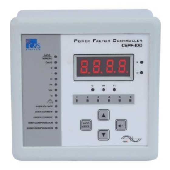
Page 3: Front Interface
Reduced Electric Utility Bills Increased System Capacity Reduction of Power Losses Front Interface The front interface of CSPF-100 consists of LED for indication / Status, seven segment display and 4 keys to navigate, view, edit and save programmable parameters. OWER ACTOR... - Page 4 6 Steps CSPF-100-R06-220 8 Steps CSPF-100-R08-220 12 Steps CSPF-100-R12-220...
- Page 5 Dimension Details All the dim. are in mm (Gen. Tol.: + 1.0mm) Front View Side View Mounting Clamp 63.0 144.0 69.0 80.0 Panel cut out Back view of CSPF 138.0...
- Page 6 Connection To safely use of CSPF-100, it is important that people installing or handling it, follow the usual safety precautions. • Care must be taken with the capacitors, which may be charged and may discharge even after voltage is removed. Ensure that the capacitors have had time to discharge.
- Page 7 RELAY EXT. CT SUPPLY Capacitor Bank Capacitor Contactors Capacitor Contactors K9 K10 K11 K12 CSPF-100-R12-220 : 12 Relay Output contacts for capacitor bank Terminal Description Term. No. Connection Name Connection Description Aux Supply (P) Phase for control supply Aux Supply (N)
- Page 8 Programmable Parameters Basic Setting Table-1 Parameters Display Setting Range Step Unit Default Size Ø Target Cos 0.80 -0.80 0.01 1.00 C/K Ratio 0.03 02.00 0.01 0.04 External CT Ratio 9999 Bank switch ON delay t.on 9999 Switching program selection PEmS PE 1 PE 9 PE 1...
- Page 9 (B) Alarm Parameters Table-3 Parameters Display Setting Range Step Unit Default Size Over Voltage setting oURU Over Voltage Alarm delay DELY Capacitor Bank Trip selection on Over voltage Over current Setting oURC %%In Over current Alarm Delay DELY Capacitor Bank Trip selection on Over current Under current Setting vNDC...
- Page 10 Human Machine Interface (HMI) Screen AUTO/Manual mode will be indicated by Auto/Manual LED. HMI parameters will be edited or viewed going through different screens using & keys. Below are the brief overview of the menu structure. UP/+ DOWN/- ENTER/SAVE Scroll Keys &...
- Page 11 Sub Menu Screens for A1 In Edit /View setting option user can view or edit the settings after entering the password (Default : P100). Refer Programmable Parameters (Basic Setting) on Page 8 for detailed information. Scroll Keys Switching program selection Return to Prev Menu Target Power Factor C/k Ratio...
- Page 12 To change the setting of any of these above shown parameters, User can select the desired one by Pressing key. Already set value will be displayed. Press to edit the setting. The value will start flashing. Short Press Short Press Then use keys to change the value and then press key to save the changed value.
- Page 13 Technical Data Network Type 3 Phase - 3 Wire / 3 Phase - 4 Wire Aux-Supply 140 - 265V AC / DC, 50 / 60Hz, 12VA Sensing/Measurement True RMS Operating Voltage Voltage input : L-N or L-L Range : 50 to 500V AC; 50/60 Hz Operating Current 40mA - 7.5A ( /5A Current Transformer) Relay Output Contact...
-
Page 14: Connection Scheme
C/k value for different CT and capacitor value. Power of 1st Capacitor Step in kVAr (Q) EXT CT CT Ratio 12.5 15 50/5 0.25 0.50 1.00 75/5 0.17 0.33 0.67 0.83 1.00 100/5 0.13 0.25 0.50 0.63 0.75 1.00 150/5 0.08 0.17 0.33 0.42 0.50 0.67 0.83 1.00 200/5 0.06 0.13 0.25 0.31 0.38 0.50 0.63 0.75 1.00... - Page 15 VOLTAGE CURRENT VOLTAGE CURRENT SUPPLY SUPPLY 11 12 11 12 Vin ~ Vin ~ (AnEL) (AnEL) PHASE ANGLE : 240 PHASE ANGLE : 330 VOLTAGE CURRENT VOLTAGE CURRENT SUPPLY SUPPLY 11 12 11 12 Vin ~ Vin ~ (AnEL) (AnEL) PHASE ANGLE : 60 PHASE ANGLE...
- Page 16 2. Refer the C/k ratio value in basic setting in Alarm achieved page 8. 1. In Manual mode Auto/Manual Led will be ON CSPF-100 is in Manual No capacitor in Manual mode user has to press up/down key Mode / Loose steps are...
Need help?
Do you have a question about the CSPF-100 and is the answer not in the manual?
Questions and answers
How do i put it in manual mode
To set the C&S CSPF-100 to manual mode, use the UP and DOWN keys to manually connect or disconnect the capacitor steps.
This answer is automatically generated