Advertisement
Quick Links
Introduction
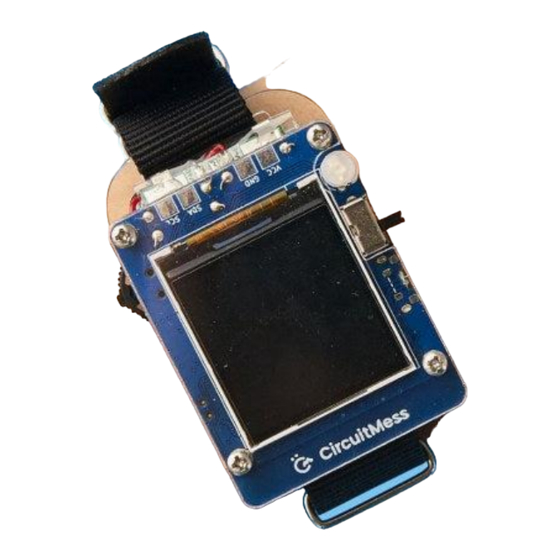
Welcome to CircuitMess Clockstar build guide!
By following this build guide, you'll learn how to assemble your new DIY smartwatch.
With Clockstar, you'll learn about AI and machine learning, edge computing, Bluetooth and
wireless communication, gyroscopes, accelerometers, motion detection, and much more.
Age group
Like it says on the box, Clockstar is designed for anyone who's at least 11 years old.
You should approach some of the assembly steps carefully, so make sure to have an adult
Advertisement

Subscribe to Our Youtube Channel
Summary of Contents for Circuitmess Clockstar
- Page 1 Age group Like it says on the box, Clockstar is designed for anyone who's at least 11 years old. You should approach some of the assembly steps carefully, so make sure to have an adult...
-
Page 2: Assembly Time
So hold on tight, read all the instructions, and get ready to have fun! This is a great opportunity and your first step in your big engineering career. Learning with Clockstar As previously mentioned, Clockstar will teach you a few useful things in the following few hours. Here's what you'll learn: ●... -
Page 3: What's In The Box
In case something is missing, please contact us at contact@circuitmess.com. Send us a photo of everything that came in the box, and we'll get back to you as soon as... - Page 4 Here's the list of components: 1. Main circuit board 2. Acrylic casings 3. Watch strap 4. RGB LED diode 5. Resistors 6. Switch 7. Long metal screws (4) 8. Long spacers (4) 9. Small spacers (4) 10. Small metal screws (4) 11.
- Page 5 If you have your CircuitMess Tools pack in front of you, you should be all set! In case you got the Clockstar kit without the Tools pack, this is a good time to borrow some of the tools or purchase them.
-
Page 6: Soldering Iron
2. Cutter pliers 3. Small screwdriver 4. Replacement soldering tips 5. Lead-free solder 6. Soldering stand 7. Sponge 8. Soldering iron Soldering iron This is the most important tool in a maker’s arsenal. For Clockstar's assembly, any entry-level soldering iron will suffice. - Page 7 If you plan to dive into the world of DIY projects, you should consider getting a more expensive one with more features. Many soldering irons with interchangeable tips can be particularly useful when working with much smaller components. In the next chapter, you'll find the instructions on how to properly solder and take care of your soldering iron.
- Page 8 We prefer this type shown in the picture (Plato, model 170), but any other type will do. Standard cross screwdriver You’ll need this cross (Phillips) screwdriver to assemble the casing. A standard 2.0mm cross screwdriver should do the trick.
- Page 9 Learn to solder The first thing that you'll do as a part of the Clockstar assembly process is soldering! Have you ever done that before? If your answer is no, we suggest you look at the following few links, where you'll find useful tutorials and blogs about soldering. It will only take you 10 minutes to get into the zone and understand how it's done.
- Page 10 ● Sparkfun’s standard soldering tutorial - A detailed tutorial made by Sparkfun. There are several rules of soldering that everybody, regardless of their skill level, should follow at all times. ● Never inhale the dust and the fumes that can be produced by the soldering iron! These can be hazardous, so please don't inhale them.
- Page 11 one hand and wipe the tip of the soldering iron on the other part of the sponge to remove the extra solder. Repeat the process until the tip of the iron is nice and clean from the old solder. ● Check your solder joints twice (at least)! Most of the malfunctions in the world of electronics are due to bad solder joints, so regardless if this is your first or 100th soldering project, always make sure to inspect your joints multiple times before proceeding to the next step.
- Page 14 Using the soldering iron The soldering iron is very easy to use but only when used properly. If you have purchased the CircuitMess tools pack with your Clockstar kit, you have gotten a the soldering iron with it. Remember the rules mentioned previously? Good! Let's go over the instructions on how to use the soldering iron now…...
- Page 15 The soldering iron is very easy to use but only when used properly. Step 1 - plug it in Put the soldering iron on a soldering iron stand, and plug it into a power outlet. Step 2 - Select the right temperature The temperature will set to 390 degrees Celsius by turning the soldering iron on.
- Page 16 Step 3 - Don't forget to turn it off when you're finished We’ll tell you when you’re done with soldering, and you'll unplug the iron from the power outlet to turn it off. Please use the metal stand every time you are not using the soldering iron to make sure you don't burn the surface or the circuit board.
- Page 17 Make sure not to touch the soldering iron tip for at least five minutes after you have turned it off. Solder your Clockstar Now you know how to solder, let's put it to the test. Ready? Part one - Soldering the resistors...
- Page 18 Resistors are the most basic electronic components found in almost every electronic device. They just modify the flow of electrical energy in their own unique way. The resistors that you have gotten in your package have a cylindrical shape and two tiny metal legs.
- Page 19 Make sure it's on the right side (the back) so you can solder it on the front.
- Page 21 Take the soldering iron, and begin to solder.
- Page 22 After you've done, check if the soldering joints look good. Using the pliers, cut the remaining legs of the resistor. To protect your eyes, turn the board away from your face when cutting.
- Page 23 Take another resistor, and put it next to the first one. This one will also be soldered on the front.
- Page 25 Start soldering.
- Page 26 And, finally, place the last resistor here:...
- Page 28 You must be careful not to touch the display with the tip of the soldering iron, since this will melt it.
- Page 29 This is what your Clockstar should look like when you cut the resistor legs:...
- Page 31 Part two - Soldering the switch Make sure all the soldering joints on the resistors are looking good before proceeding. If they are, take the switch.
- Page 32 This is where you should place the switch. This component will be soldered at the back of the PCB.
- Page 33 The first and last soldering joints are the easiest to solder. Make sure that the switch is pushed all the way to the board and that it's not tilted.
- Page 35 Check the soldering joints and make sure that there are no bridges made. If they are, you must clean them. Otherwise, your Clockstar will not turn on. Part three - Soldering the LED Now is the time to solder the LED.
- Page 36 On the PCB, you can see the "cut-off" part drawn where the LED should go. Your LED's head also has a somewhat cut-off part. You must ensure that the parts are aligned.
- Page 37 The LED will be on the front, so the soldering will take place at the back.
- Page 38 LED does not have to go all the way to the board. Don't push it too hard or it will break.
- Page 39 You can cut the rest of the LED's legs if all of the soldering joints appear clean and there are no bridges.
- Page 41 Check all of the soldering joints again before moving on to the next chapter, where we'll continue assembling Clockstar. Time for the casings Welcome to the chapter where you'll see how to assemble the casing for your Clockstar! Let's take two square-shaped acrylic casings.
- Page 42 The first thing you need to do is to peel off the white protective layers. As you can see, each of the acrylic casing parts has a protective layer on both sides that needs to be peeled off. They are not yet fully transparent, but they should be once you finish this step!
- Page 43 This is what the casings should look like once you remove all the protective layers:...
- Page 44 Take the upper casing from the photo above, four longer screws and four smaller spacers. Put the screw through the casing like this:...
- Page 45 If you're not sure which side to put the screws on, you can check it by placing it on the PCB. This one will be placed in the front, and the cut-off part is where the switch will go. Add the spacer. Fasten it with your fingers.
- Page 46 Repeat this process for all four screws.
- Page 47 Take the second casing, four smaller screws, and four bigger spacers.
- Page 48 This one will be placed on the back. Put the screws through the casing like this:...
- Page 49 Put the spacer on the other side and fasten it with your fingers.
- Page 50 Repeat this step for all four screws.
- Page 51 Now is the time to remove the protective foil from the display.
- Page 52 Put this aside for a bit and take the battery.
- Page 53 This is where you'll connect it with the PCB:...
- Page 54 Remove the sticky yellow pad from the battery:...
- Page 55 Put the sticky side of the battery on the back casing, like this:...
- Page 56 Now, put the casings on the PCB.
- Page 58 Take the screwdriver to attach the casings one to another. This is what your Clockstar should look like by now:...
- Page 59 Now is the time to add the watch strap.
- Page 60 Pull the strap through like this:...
- Page 61 And now, pull the strap through the second hole on the casing.
- Page 62 Like this:...
- Page 63 Take part with the holes, and pull it through the metal part:...
- Page 64 Ta-daaa!
- Page 65 Put it on your hand, turn it on, and have fun!
-
Page 66: What's Next
Congrats! You successfully soldered your DIY smartwatch - Clockstar. What's next? Congratulations! You successfully assembled a DIY smartwatch, Clockstar. The next thing you'll have to check is how to use it, and what amazing features we prepared for your, and how to code it! - Page 67 We are currently in the process of creating coding and usage guides, so we'll have to ask you for a bit more patience. In the meantime, we invite you to join our Discord channel Facebook group where you'll be able to share ideas, photos, and feedback with fellow makers and get exclusive news from CircuitMess.
Need help?
Do you have a question about the Clockstar and is the answer not in the manual?
Questions and answers