Advertisement
Quick Links
AC Variable Frequency Drive
Hayward Commercial Aquatics
USE ONLY HAYWARD GENUINE REPLACEMENT PARTS
Owner's Manual
Contents
Before you Begin...................3
Installation............................4
Operation.............................8
Troubleshooting...................12
421501P
520201P
520251P
620301P
Hayward Industries
400 Connell Drive, Suite 6100
Berkeley Heights, NJ 07922
Phone: (908) 355-7995
www.hayward.com
620401P
620501P
620601P
1004021 RevA
Advertisement

Related Manuals for Hayward 421501P

Summary of Contents for Hayward 421501P
- Page 1 Hayward Commercial Aquatics Owner's Manual Contents Before you Begin....3 Installation......4 Operation......8 Troubleshooting....12 421501P 620401P 520201P 620501P 520251P 620601P 620301P Hayward Industries 400 Connell Drive, Suite 6100 Berkeley Heights, NJ 07922 Phone: (908) 355-7995 www.hayward.com USE ONLY HAYWARD GENUINE REPLACEMENT PARTS...
- Page 2 WARNING – Failure to keep suction outlet components clear of debris, such as leaves, dirt, hair, paper and other material can result in an increase potential for suction entrapment as described above. USE ONLY HAYWARD GENUINE REPLACEMENT PARTS...
- Page 3 5 ft. (1.5 m) of inside walls of swimming pool, spa, or hot tub. IMPORTANT - Reference NEC codes for all wiring standards including, but not limited to, ground- ing, bonding and other general wiring procedures. USE ONLY HAYWARD GENUINE REPLACEMENT PARTS USE ONLY HAYWARD GENUINE REPLACEMENT PARTS...
-
Page 4: Before You Begin
Size 5 & 6 = for 1 phase HP x 2, for 3-phase HP x 1 3- Phase Supply Single Phase Supply Model Motor HP Model Motor HP HCPVFD421501P HCPVFD421501P HCPVFD520201P HCPVFD520201P HCPVFD520251P HCPVFD520251P 12.5 HCPVFD520251P HCPVFD620301P HCPVFD620401P HCPVFD620401P HCPVFD620501P HCPVFD620501P HCPVFD620601P HCPVFD620601P USE ONLY HAYWARD GENUINE REPLACEMENT PARTS USE ONLY HAYWARD GENUINE REPLACEMENT PARTS... -
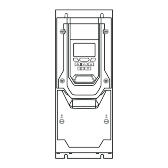
Page 5: Installation
Specifications Refer to the diagram below and the table on page 5 for dimensions of the VFD. Refer to your model number for the Drive Size (page 3). USE ONLY HAYWARD GENUINE REPLACEMENT PARTS USE ONLY HAYWARD GENUINE REPLACEMENT PARTS... - Page 6 For 3 phase supply, the mains power cables should be connected to L1, L2, and L3. Phase sequence is not important. NOTE: The motor cable length should not exceed 300 feet (100 meters). If longer cable lengths are necessary, please contact Hayward for additional installation requirements. USE ONLY HAYWARD GENUINE REPLACEMENT PARTS USE ONLY HAYWARD GENUINE REPLACEMENT PARTS...
- Page 7 Class J fuses. Mechanical Installation Requirements All drive units are intended for installation within controlled environments which meet the condition limits shown in the Environment section of this manual. USE ONLY HAYWARD GENUINE REPLACEMENT PARTS USE ONLY HAYWARD GENUINE REPLACEMENT PARTS...
- Page 8 STO- RL1-C RL1-NO RL1-C Relay Output 1 Common RL1-NC RL1-NO Relay Output 1 Normally Open RL2-A RL1-NC Relay Output 2 Normally Closed RL2-B RL2-A Relay Output 2 Relay Output 2 RL2-B Drive Control Terminals USE ONLY HAYWARD GENUINE REPLACEMENT PARTS...
-
Page 9: Operation
Used to decrease speed in real-time mode or to decrease parameter values in parameter edit DOWN mode. Used to display real-time information, to access and exit parameter edit mode and to store NAVIGATE parameter changes. RESET /STOP Used to reset a tripped drive. USE ONLY HAYWARD GENUINE REPLACEMENT PARTS... - Page 10 The display will show the The display will show the motor speed (RPM). Refer to section 4.14.8. Press the Navigate key to motor current (Amps). motor power (kW). Recommended “STO” select alternate displays. Wiring on page 31. USE ONLY HAYWARD GENUINE REPLACEMENT PARTS...
- Page 11 Technical Data Operational ambient temperature range IP55, NEMA 12 drives: -20 ... 40°C (frost and condensation free) Storage Temperature: -40 … 60°C Maximum Altitude: 2000m. Derate above 1000m: 1% / 100m Maximum Humidity: 95%, non-condensing USE ONLY HAYWARD GENUINE REPLACEMENT PARTS...
- Page 12 Size (Amps) 50.1 HCPVFD421501P 63.9 HCPVFD520201P 18.5 25 74.0 HCPVFD520251P 99.1 125 125 150 300MCM HCPVFD620301P 121.0 160 150 150 300MCM HCPVFD620401P 159.7 200 200 150 300MCM HCPVFD620501P 163.4 200 200 150 300MCM HCPVFD620601P USE ONLY HAYWARD GENUINE REPLACEMENT PARTS...
-
Page 13: Troubleshooting
OUt-F Output Fault NOTE: Following an over current or overload trip (3, 4, 5, 15), the drive may not be reset until the reset time delay has elapsed to prevent damage to the drive. USE ONLY HAYWARD GENUINE REPLACEMENT PARTS... - Page 14 Press and hold the Up, The display shows U-Def. The display returns to Briefly press the Stop key. Stop. All parameters are Down, and Stop keys for > 2 seconds. reset to Factory defaults. USE ONLY HAYWARD GENUINE REPLACEMENT PARTS...
- Page 15 USE ONLY HAYWARD GENUINE REPLACEMENT PARTS...
- Page 16 Hayward is a registered trademark of Hayward Industries, Inc. © 2022 Hayward Industries, Inc. All other trademarks not owned by Hayward are the property of their respective owners. Hayward is not in any way affiliated with or endorsed by those third parties.
Need help?
Do you have a question about the 421501P and is the answer not in the manual?
Questions and answers