Advertisement
Quick Links
Advertisement

Summary of Contents for OE Max Controls PGM-500
- Page 1 Maximum Value for OEMs Hand-held Programmer (PGM-500) User Manual...
- Page 2 Maximum Value for OEMs Hand-held Programmer (PGM-500) User Manual Contents English ........3 中文 ........77...
-
Page 3: Table Of Contents
English Contents 1. Overview ..............7 2. Programming Procedure .......... 17 3. Programming Key Operation ........35 4. Basic Operating Procedures ........43 5. Function Operation ........... 61 A. Appendix ..............71... - Page 4 Important User Information Solid state equipment has operational characteristics differing from those of electromechanical equipment. Because of this difference, and also because of the wide variety of uses for solid state equipment, all persons responsible for applying this equipment must satisfy themselves that each intended application of this equipment is acceptable.
- Page 5 Safety Instructions Please read this manual and the related documentation thoroughly and familiarize yourself with product information, safety instructions and other directions before installing, operating, performing inspection and preventive maintenance. Make sure to follow the directions correctly to ensure normal operation of the product and your safety.
-
Page 7: Overview
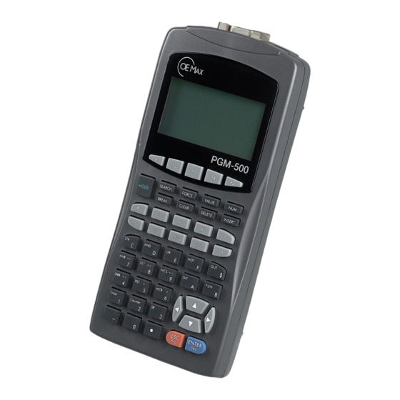
Overview Part Description Dip Switch LCD Display Keypad Comm. Connector External Power Jack Hook Dummy Cover Textool Connector... - Page 8 Temperature -20 °C to +60 °C Storage Operating Humidity 30 to 85% RH Storage PGM-500 2.15 VA (Max 430mA X 5Vdc) Power Consumption PGM-WR 0.25 VA (Max 50mA X 5Vdc) Capacitor Back-up for 10 days at 25 °C Memory Backup...
- Page 9 Keys Configuration Function Keys SEARCH FORCE VALUE MODE Operation Keys BREAK CLEAR DELETE INSERT Register Keys Instruction & Numeric Keys ANB== SET>= MCS<= ORB<> RST> MCR< Arrow & Timer Counter Execution Keys ENTER Function Keys Function PLC Control (ESC combination) Search Value Change Special key is used to select menu after pressing function...
- Page 10 Operation Keys Functions MODE Select programming mode and monitoring mode (Toggle) SEARCH Search register/number/step, command FORCE Forced output VALUE Change current register value Convert and select the value of Decimal & Hexadecimal (Toggle) BREAK One Scan Run (run at PAUSE & REMOTE) CLEAR Clear all the program, when clearing on editor DELETE...
- Page 11 Instruction & Numeric Keys Description Start rung, Normal Open C (Character, Number) Normal Open series contact D (Character, Number), Double Word Symbol Normal Open parallel contact E (Character, Number) Reversing of rung logic F (Character, Number) Realy Out $ (Symbol for input hexadecimal number) Blocks in series, Equal 7 (Character, Number) >=...
- Page 12 Mode Description PGM-500 has following 3 modes. They are EDT (Edit), MON (Monitoring), SYS (System), and you can move between EDT and MON modes using key, and between MODE EDT and SYS, or MON and SYS modes, you can move through combining keys.
- Page 13 When the running programs of PLC is wrong, 3 (PLC S/W display) and 4 (Status display) show READY. Offline Programming Screen display Functions Functions Functions Mode display Instruction display Message & menu display Offline status display Scroll status display Step number display Operand input/display Functions Program search...
- Page 14 Supporting functions Monitor register ● Search register (word) ● Forced output ● Change the value of register ● Convert the value of decimal & hexadecimal of monitoring ● Run the 'SCAN RUN' (Refer to “Scan Run” on page 59.) ● Control PLC (On/Off/PLC connection ) ●...
- Page 15 Inform and control information of PLC system ● Inform and control information of Backup memory ● Inform and control information of Option Pack (Flash memory) ● Inform and control information of PGM-500 system ● Menu Item Description • Inform PLC/CPU/ROM version INFORM •...
-
Page 17: Programming Procedure
Programming Procedure Programming Sequence Connection Power supplying 1. Connect PGM-500 to CPU module of PLC on RS-232 or RS-485 by using cable. 2. Supply PGM-500 with power by using AC adapter. • When connection of power is good, LCD is bright with a buzzer. - Page 18 Initial Configuration Input CPU ID and set on/off line ● Input ID on on-line (Not inputting, move the next screen.) ● 1. Input CPU ID for On-line connection. 2. Press ESC key at off-line. • No danger of backward current though connecting to PLC by external power.
- Page 19 ● In on-line mode, the program loaded in the working IMPORTANT memory of PGM-500 is the same with the program now run by PLC. Modification of working memory will change the program run by PLC. When connecting in Online mode ●...
- Page 20 1. In order to communicate with connected PLC, input the CPU Id of PLC you want to connect. • As the program is not loaded in the working memory of PGM-500 , you should upload program from PLC. • Refer to Chap. 4. Basic operating procedures necessary for programming.
- Page 21 Select off-line at the initial setting. ● Select the type of PLC & CPU which you want to program. (for ● example, PLC is NX7) 1. Move into PGM-500 setting menu. 2. Set programmable PLC information. 3. Select programmable PLC. 4. PLC series...
- Page 22 5. Select NX7. 6. Select CPU module. 7. Select CPU7. 8. Information about PLC Move into EDIT mode. (Programming is the same as online.) ● • Program name is used with number 0~9 and character A~F, Refer to 5.10. • For mode move, refer to A.2.
- Page 23 Program Download What is Download? ● It is a process to write program in the working memory of PGM-500 into memory of PLC. If you want to download program in the Backup or Pack memory to PLC, you can download it after writing it into the working memory of PGM-500.
- Page 24 4. Select DOWN LOAD menu (MEM => PLC). 5. Download program from working memory of PGM-500 to PLC. 6. Check after moving to EDT MODE. As the job under off-line mode is usually stored in Backup memory and Flash memory of Pack, you can use it freely if you understand following described fully in “Programming Transfer”...
- Page 25 When you connect in Online mode, the program of PLC is ● automatically copied into working memory of PGM-500. The procedure to load program in PLC into working memory of PGM-500 will be described hereafter. 1. Input the CPU Id of PLC you will connect.
- Page 26 If you connect PLC by inputting CPU ID in Offline mode, you can only use SYS mode and MON mode. You must have PLC program loaded in working memory of PGM-500 to use EDT mode, therefore you need to unload. For detailed operation of keys, refer to “Keys Configuration”...
- Page 27 Program Backup What is Backup? ● It is a process to store program in working memory of PGM-500 to backup memory, or to bring program in backup memory to working memory. The procedure is same for both online and offline. The procedure to ●...
- Page 28 3. Store in BACKUP memory. Reading backup memory 1. Select BACKUP menu. 2. Select PROGRAM menu.
- Page 29 3. Load from BACKUP memory. You cannot download program in backup memory directly IMPORTANT into PLC. Therefore, you should download what is in working memory to PLC after loading program in backup memory to working memory of PGM-500.
- Page 30 Memory Pack What is memory pack? ● You can save program in working memory of PGM-500 into memory pack, and bring program in flash memory into working memory. The procedure is same for both online and offline programming. ● The procedure to save into memory pack will be described in online mode, and to load it from memory pack to working memory will be described in offline mode.
- Page 31 3. Save into FLASH memory. Loading from FLASH memory into working memory 1. Select PACK menu. 2. Select PROGRAM menu.
- Page 32 3. Load from FLASH memory. You cannot save program saved in memory pack directly IMPORTANT into backup memory. Therefore, load program in memory pack into working memory first, then save what is in working memory into backup memory. You may also download into PLC.
- Page 33 Back-up Memory to PLC 1. Connect to PLC. 2. Move to SYSTEM mode (offline). 3. Move to BACKUP. 4. Select MEM <= BACKUP 5. Connect to PLC at initial screen of SYSTEM (ESC+F3). 6. Move into program of PLC-CPU. 7. Select MEM => PLC Back-up Memory to Memory Pack 1.
-
Page 35: Programming Key Operation
Programming Key Operation Basic Instruction STR D== STR D<> AND D< D< STR D== <> STR D<> >= <= AND D< > < D< STR DIF STR DIF STR DFN STR DFN 3-1 Combining basic instructions For STR, AND, and OR commands, You can make command IMPORTANT by combing DIF, NOT, and comparative sentence. - Page 36 Mnemonic Names Keys Functions Start a contact start Start Not b contact start a contact serial circuit And Not b contact serial circuit a contact parallel circuit Or Not b contact parallel circuit Output arithmetic result Circuit inversion STR DIF Start Differential Up edge contact start STR DFN...
- Page 37 Comparison Instruction Mnemonic Names Keys Functions ANB== STR (D)== When the left value is ANB== AND (D)== EQUAL equal to right value, ON. OR (D)== ANB== ORB<> STR (D)<> When the right value ORB<> AND (D)<> NOT EQUAL and left are not equal, OR (D)<>...
- Page 38 Timer/Counter/SR instruction Mnemonic Names Keys Functions On Delay Timer On delay timer Timer Single Shot Timer Single shot timer Off Delay Timer Off delay timer Up Counter Up counter Down Counter Down counter Counter Up-Down Counter Up/down counter Ring Counter Ring counter Shift Register Shift register...
- Page 39 Application Instruction Group Class Descriptions SHIFT FUN-0XX Shift instructions MOVE FUN-1XX Block Move instructions FUN-2XX Bit instructions. CONTROL FUN-3XX Program control instructions LOGICAL FUN-4XX Logical computing instructions ARITHMETIC FUN-5XX Arithmetic computing instructions CONVERTER FUN-6XX Data converter instructions FUN-7XX BCD computing instructions SPECIAL FUN-8XX Special instructions...
- Page 40 Examples Let's take example of inputting ADD command. Input when you do not know CLASS or the location of command Key Input Order Screen display Note • The screen beside will be displayed if you add command at the end of program. •...
- Page 41 When you know the exact code of application command Key Input Order Screen display Note • The screen beside will be displayed if you add command at the end of program. • If you change application command, it will show application command inverted.
- Page 42 Word Register Method) Register type code + number • For the types and range of register available for each type, please refer to Chapter 4 Basic Operating Procedures. Number 1. Input hexadecimal value After inputting , use number from 0 to F of hexadecimal value. 2.
-
Page 43: Basic Operating Procedures
Basic Operating Procedures Insert & Append Step Insert Step Function : Insert instructions during programming (INSERT) ● Use : On/Off line ● Program example : ● R000.00 R001.01 R002.02 M001.00 M000.00 R000.01 Step Instruction Step Instruction 00011 R000.00 00011 R000.00 00012 R001.01 00012... - Page 44 Operating procedure ● • Move to the position you will insert. SEARCH method1) Use Up and Down arrows. Timer RST> method2) Use Search F5(Go#). ENTER • Press Insert, and prepare for the step inserted before the present step. INSERT • Input the instruction •...
- Page 45 • Check the operation using direction arrows. Append Step Function : Append step at the end of program (APPEND, PLC/PGM) ● Use : On/Off line ● Program example : ● Program example : ● R000.00 R001.01 R002.02 M001.00 R000.01 M000.00 Step Instruction Step...
- Page 46 Operating procedure ● • Move to the end of SEARCH program. method1) Use Up and Down arrows. Timer method2) When using search function, run step search, and input larger value than final step. ENTER • When you add step, you can use both insert and enter.
- Page 47 Change Step Function : Change current instruction of step ● Use : On/Off line function ● Program example : ● R000.00 R001.01 R002.02 M001.00 M000.00 R000.01 Step Instruction Step Instruction 00010 R000.00 00010 R000.00 00011 R001.01 00011 R001.01 00012 M000.00 00012 M000.00 00013...
- Page 48 • Input command you will modify. • Finish inputting a instruction [Note] If you want to ENTER modify only command, not operand, press enter and finish. • Modify operand. Timer • Complete modification. ENTER...
- Page 49 Delete Step Function : Delete current step (DELETE, PLC/PGM) ● Use : On/Off line ● Program example : ● R000.00 R002.02 K015.04 M015.02 Step Instruction Step Instruction 00010 R000.01 00010 R000.01 00011 K015.02 00011 K015.02 00012 R002.02 00012 K015.04 00013 K015.04 Figure 4-4 Delete step Operating procedure...
- Page 50 ESC. • Screen after deleting PLC program by pressing ENTER, It will ENTER ask you to delete program in the memory of PGM-500. • Screen after deleting program in PGM by pressing ENTER ENTER • PGM program undeleted as you press ESC.
- Page 51 Search Function : 1. Search T/C channel. ● 2. Search bit/word register. 3. Search number. 4. Goto step. Use : On/Off line ● If you have searched before, it'll be displayed in the search window. T/C Channel • Press SEARCH key •...
- Page 52 • If you press any key, it will show the currently searched step. • Even though you select No for " REPEAT SEARCH?", it'll show the currently searched step. Bit & Word Register • Press SEARCH. • Five menus will be displayed at the bottom.
- Page 53 Number • Press SEARCH SEARCH • Press F4 corresponding to NUM. • If there is no item searched before, only blank will be displayed. • Input the value you want to search. Timer RST> • If you run it, it will search from the closest step.
- Page 54 Go To Step • Press SEARCH SEARCH • Press F5 corresponding to GO TO STEP. • It will be differently expressed according to the NUM mode of previous search (Hexa or DEC.) • Input the step value you want to go to. Timer RST>...
- Page 55 Forced Output Function : Forecd output insert/ delete/ change/ all clear ● Use : On line ● Insert • FORCE TABLE Display ex) No current setting. FORCE • Set forced output bit. INSERT ENTER • Input bit register ex) Input R000.00 ° For operand in- put, refer to 3.5.
- Page 56 Change • FORCE TABLE Display ex) Setting screen display. FORCE • Transfer to forced output bit with direction key. ex) Transfer to K000.01 • Select item to change ex) Select K000.01 ENTER • Change setting value -> ex) Set Reset ENTER •...
- Page 57 Delete • FORCE TABLE Display ex) Show the value to be changed FORCE • Transfer to forced output bit to change with direction key. ex) Transfer to K000.01 • FORCE TABLE Display ex) Setting screen after deleting DELETE All Clear •...
- Page 58 Value Change Function : Forced output insert/ delete/ change/ all clear ● Use : On line ● F1:BIT, F3:WORD, F5:DOUBLE WORD, the cancel key is ESC. • Value Change setting display • Setting display after deleting VALUE • Change the value of bit register •...
- Page 59 Transfer with direction key After running one cycle • BREAK Through running internal clock of PLC, PGM-500 cannot operate Scan Run. PLC Status Control Function : PLC RUN/STOP & connection target PLC change ● Use : On line (PLC s/w is RUN/RMT) ●...
- Page 60 RST> • Operate PLC control ENTER In case PGM-500 constitute one network connected to many PLC, appoint CPU ID of PLC you want to connect, in order to connect PLC. If you set CPU ID to 255, you will be...
-
Page 61: Function Operation
Function Operation System configuration is composed of following menu structure. If you move in the same screen, use UP and DOWN key, and use ESC to go to the upper level menu, and enter to select lower level menu. SYSTEM CONFIGURATION PLC-CPU INFORM... - Page 62 PLC - Read Information (INFORM) You can know the connected PLC and program information, and it has following menu. Show the types of connected PLC, and followings are PLC you can connect. Series 10, 24S,100, 120S, 300 Series 200 Series 70, 700 Show the type of CPU of connected PLC.
- Page 63 " > " marky, you can operate it. If it doesn't have, you can make query only. MEM => PLC Write program in working memory of PGM-500 into PLC. (Down Load) MEM <= PLC Copy program operated in PLC into working memory of PGM-500. (Up Load).
- Page 64 OUT UPDATE Decide whether you write the result of execution of PLC code by CPU module into output register. OUT ENABLE Decide whether you will output the contents of output register to contact point of output module. TIME INTR. Decide whether you will use application command. [INT] KEEP CLEAR Decide whether you will delete the contents of KEEP register.
- Page 65 RTC TIME You can input or see the time of Real time clock. RMF CONF. You can set and inquire romote. (Refer to RMU/RSU User's Manual.) I/O CONF. You can set and inquire I/O address.(Refer to A200 User's Manual.) PLC - Check System & Program (CHECK) System and syntax check on connected PLC, and error table about it.
- Page 66 Back-up - Read Information (INFORM) Show the information about PLC program saved in power suspension maintenance area set in the PGM-500. Show the type of PLC used for PLC program saved in backup memory. Show the type of CPU module of PLC used for PLC program saved in backup memory.
- Page 67 Back-up - Manage Program (PROGRAM) Upload PLC program in backup memory into working memory of PGM-500, or save PLC program of working memory into backup memory. MEM => BACKUP Save PLC program in working memory of PGM-500 into backup memory.
- Page 68 Show the name of program saved in PACK memory. PACK - Manage Program (PROGRAM) Inquire information about PLC in working memory of PGM-500, or set PLC information for programming. Show the PLC used for program, and set PLC you will work on.
- Page 69 PGM - General Control (CONTROL) BAUD RATE Show present communication speed. BACKLIGHT Execute on/off of BACK LIGHT. BEEP SOUD Set on/off of BEEP SOUND. POWER SAVE Set Power Save mode. Power save mode will not be operated if it is '0', and you can set from the minimum 1 min.
-
Page 71: Appendix
Fail to loading of system driver A/S inquiry ILLEGAL DIP SETTINGS Wrong position of DIP s/w TARGET SERIES CHANGED PLC of PGM-500 and target PLC is different. Reconnection INTERNAL MEMORY ERROR Error in the internal memory of PGM-500 A/S inquiry... - Page 72 Online Error Error message Description Action CPU MODULE MISMATCHED Not matched to CPU module PLC check UNUSABLE CPU ID Unusable CPU ID 0~255 input NOT FOUND CPU MODULE Not connect to PLC DIP s/w check PASSWORD MISMATCHED Wrong ID ILLEGAL REMOTE CONFIG Wrong remote setting ILLEGAL I/O CONFIG Wrong I/O setting...
- Page 73 Operating Procedure Basic Operating Order of Online Mode Functions Operating Order Reference • EDT MON MODE But, the program must be PGM • EDT • But, the program must be PGM. Mode modifying MODE [EDT|MON|SYS] • MON MODE • PLC RUN •...
- Page 74 Basic Operating Order of Offline Mode Functions Operating Order Reference • EDT Mode modifying MODE But, program must be set. [EDT] • Select PLC-CPU to communicate PLC NETWORK [EDT|MON|SYS] • Move to up-step • Move to down-step STEP moving [EDT| STEP insert •...
- Page 75 FORCE Forced output delete [EDT|MON| DELETE • All clear forced output TABLE ALL CLEAR FORCE CLEAR [EDT|MON| Operation Between PGM-500 And PLC Functions Operating Order Reference • DOWN LOAD to PLC |SYS] • UP LOAD from PLC |SYS] CLEAR PLC •...
- Page 76 PGM-500 Control Functions Operating Order Reference • PLC STOP RUN • PLC RUN STOP PLC RUN/STOP |SYS] • Backlight ON/OFF (Toggle) BACKLIGHT ON (PGM-500 CONTROL BACK LIGHT) ENTER |SYS] • BEEP SOUND ON/OFF BEEP ON/OFF ENTER (PGM-500 CONTROL BEEP |SYS]...
- Page 77 1. 概述 ................81 2. 编程过程 ..............91 3. 编程键操作 ..............109 4. 基本操作过程 ............117 5. 功能操作 ..............135 A. 附录 ................145...
- Page 78 重要用户信息 固态电子设备的运行特性不同于机电设备。由于存在这种差异,而且由于固 态电子设备具有各种不同的用途,因此所有负责应用该设备的人必须保证此 设备的每种预期用途都是可以接受的。 在任何情况下, OE M Controls 对因使用或应用此设备导致的间接损害或 继发性损害均不承担任何责任。 本手册中包含的示例和图示只用于说明目的。由于任何特定安装都具有许多 相关的可变因素和要求,因此, OE M Controls 不对基于示例和图示的实 际使用承担任何责任。 至于使用本手册中描述的信息、电路、设备或软件, OE M Controls 不承 担任何专利责任。 如果没有 OE M Controls 的书面批准,禁止全部或部分复制本手册的内 容。 在整个手册中,我们将使用各种标记来提醒您注意安全方面的事项。 表示可能导致严重人身伤害或死亡、财产损失或经济损失的做法 或情况的信息。 表示对成功应用和了解本产品至关重要的信息。 表示可能导致轻微人身伤害、财产损失、经济损失或产品失灵的 做法或情况的信息。不过,根据实际情况,不遵守附有此符号的 指示可能也会导致严重后果。...
- Page 79 在安装、操作、进行检查和预防性维护之前,请通读本手册和相关文档,并 熟悉手册中的产品信息、安全说明和其它相关说明。务必正确遵循说明进行 操作,以确保产品正常运转和您的安全。 • 如果使用本产品的场合可能会导致人身伤害和/或使产品受到严 重损坏,请采取相应的安全保护措施,如使用安全可靠的设备。 • 不要在具有爆炸性气体的任何环境中使用本产品。否则,可能 会导致爆炸。 • 在配置应急保护断路器或联锁电路时,确保使用外部设备。 • 牢牢地拧紧端子螺钉,以确保电缆连接紧固牢靠。如果电缆连 接不正确,则可能会导致产品过热和失灵。 • 请在满足产品说明书所要求的条件下操作和保存本产品。 否则,可能导致产品过热和失灵。 • 不要拆卸或改造产品。 否则,可能导致电击危险或产品失灵。 • 电源接通时不要触摸端子。 否则,可能导致电击事故。...
- Page 81 DIP 开关 LCD 显示屏 键区 通信连接器 外部电源插头 挂钩 空盖板 Textool 连接器...
- Page 82 储存 -20 °C 至 +60 °C 运行 湿度 30 至 85% RH 储存 2.15 VA (最大值 430mA × 5Vdc) PGM-500 功耗 0.25 VA (最大值 50mA × 5Vdc) PGM-WR 电容器备份,在 25 °C 保存 10 天 存储器备份 存储器包 (PH29EE512 150-3CF、 SST) 尺寸...
- Page 83 功能键 SEARCH FORCE VALUE MODE 操作键 BREAK CLEAR DELETE INSERT 寄存器键 指令和数字键 ANB== SET>= MCS<= ORB<> RST> MCR< 箭头和执行键 Timer Counter ENTER PLC 控制 (ESC 组合) 搜索 值更改 专用键用于在按功能键之后选择菜单。...
- Page 84 MODE 选择编程模式和监视模式 (切换) SEARCH 搜索寄存器/编号/步骤以及命令 FORCE 强制输出 VALUE 更改当前寄存器值 转换和选择十进制和十六进制的值 (切换) 一次扫描运行 (在 PAUSE (暂停)和 REMOTE (远程)状态时 BREAK 运行) CLEAR 清除编辑器时清除所有程序 DELETE 删除一个步骤或删除编辑器中的一个字符 INSERT 插入一步或在编辑器中插入一个空格 NX7S NX70 外部输入/输出 0 至 127 链路继电器 0 至 255 内部继电器 0 至 127 保留继电器 0 至...
- Page 85 开始逻辑行,正常打开 C (字符、数字) 正常打开串联触点 D (字符、数字) ,双字符号 正常打开并联触点 E (字符、数字) 逻辑行逻辑取反 F (字符、数字) 继电器输出 $ (输入十六进制数字的符号) 串联块,等于 7 (字符、数字) >= 接通输出,大于等于 8 (字符、数字) <= 启动主控总线控制,小于等于 9 (字符、数字) 上升沿逻辑行 A (字符、数字) 复杂功能调用 B (字符、数字) <> 并联块,不等于 4 (字符、数字) > 关断输出,大于 5 (字符、数字) <...
- Page 86 PGM-500 具有以下 3 种模式。 它们是 EDT (编辑) 、 MON (监视)和 SYS (系统) ,您可以使用 MODE 键在 EDT 和 MON 模式之间切换,以及在 EDT 和 SYS 模式之间或者在 MON 和 SYS 模式之间切换。可以组合使用 和 键。监视可以分 MODE 为步骤监视和寄存器监视, MON 模式专用于寄存器。可以在编辑模式下对 PLC 程序进行监视。 编辑模式下有两种可以编写或编辑 PLC 程序的编程模式。第一种是联机编 程模式,在与 PLC 相连时可以上载程序,第二种是脱机编程模式,在没有...
- Page 87 模式显示 指令显示 消息和菜单显示 脱机状态显示 滚动状态显示 步骤号显示 操作数输入/显示 程序搜索 ● 程序步骤的追加/插入/删除/更改和程序的全部清除 ● 操作数搜索和定时器/计数器搜索 ● PLC 连接 ● 模式显示 状态显示 滚动状态显示 CPU ID 显示 寄存器位置 消息/菜单显示 PLC 软件显示 寄存器表...
- Page 88 监视寄存器 ● 搜索寄存器 (字) ● 强制输出 ● 更改寄存器的值 ● 转换监视的十进制和十六进制值 ● 第 页上的 “扫描运行” 运行 “扫描运行” (请参阅 。 ) ● 控制 PLC (打开/关闭/PLC 连接) ● 所选菜单的显示 状态显示 滚动状态显示 CPU ID 显示 子菜单显示 消息显示 PLC 软件显示 菜单列表 所选菜单的显示 滚动状态显示 脱机显示 菜单列表 子菜单显示部分...
- Page 89 指示和控制 PLC 系统的信息 ● 指示和控制备份存储器的信息 ● 指示和控制选件包 (闪存存储器)的信息 ● 指示和控制 PGM-500 系统的信息 ● • 指示 PLC/CPU/ROM 版本 INFORM • 指示程序大小/字/步骤 • 指示监视程序/扫描/扫描最大数目 • 程序上载/下载 PROGRAM • 程序清除 • CPU 状态控制 • 输入/输出更新 PLC-CPU • 输出启用 CONTROL • 定时器中断控制 • 保留寄存器清除控制...
- Page 91 1. 使用电缆将 PGM-500 连接到 PLC 的 CPU 模块的 RS-232 或 RS-485 上。 2. 使用 AC 电源适配器为 PGM-500 供电。 电源连接良好时, LCD 会发亮并发出蜂鸣声。 • 通过调整 DIP 开关可使 PLC 和 PGM-500 的速度相同。 •...
- Page 92 输入 CPU ID 并设置联机/脱机 ● 联机时输入 ID (不输入,则转到下一屏幕。 ) ● 1. 输入 CPU ID,进行联机连接。 2. 脱机时,请按 ESC 键。 虽然是通过外部电源连接到 PLC,但不会出现反向电流 • 危害。 当 PLC 连接良好时,将上载带有 PLC 和程序信息的作业 • 存储器。...
- Page 93 在初始设置中以联机方式连接 ● 在联机模式中, PGM-500 的工作存储器中加载的程序与 PLC 当前运行的程序相同。修改工作存储器将更改 PLC 运行的程序。 以联机模式连接时 ● 1. 使程序处于下面的状态。 2. 在联机模式下,如果在下一步工作中连接到其他已连接的 PLC,请执行以下初 始设置。请参阅 [4.9] “修改连接目标和 PLC” 。 通过 RS-485 建立连接时启用。 • 请参阅第 4 章 “基本操作过程” ,这些操作过程是编程所必 • 需的。...
- Page 94 以脱机模式连接时: ● 1. 为了与连接的 PLC 进行通信,请输入要连接的 PLC 的 CPU ID。 由于 PGM-500 的工作存储器中未加载程序,因此应从 PLC • 上载程序。 请参阅第 4 章 “基本操作过程” ,这些操作过程是编程所必 • 需的。...
- Page 95 在初始设置时选择脱机。 ● 选择要进行编程的 PLC 和 CPU 的类型。 (例如, PLC 的类型为 NX7) ● 1. 转到 PGM-500 设置菜单。 2. 设置可编程 PLC 的信息。 3. 选择可编程 PLC。 4. PLC 系列...
- Page 96 5. 选择 NX7。 6. 选择 CPU 模块。 7. 选择 CPU7。 8. PLC 的相关信息 进入编辑模式。 (编程方式与联机模式时相同。 ) ● 使用数字 0~9 和字符 A~F 来表示程序名称,请参阅 5.10。 • 有关模式切换,请参阅 A.2。 • 脱机时,即使正在编程, PLC 的程序也不受影响。 •...
- Page 97 什么是下载? ● 下载是将 PGM-500 工作存储器中的程序写入 PLC 存储器中的过程。 如果要将备份存储器或包存储器中的程序下载到 PLC,则可在 将该程序写入 PGM-500 的工作存储器中后进行下载。 在脱机模式下,要连接 PLC 需要执行一些额外的步骤,即选择要连接的 ● PLC 和 CPU,然后输入 CPU ID,如下面的步骤 1 所示。 1. 通过同时按住 ESC 键和 F3 键选择要连接的 PLC。 2. 连接 PLC 后的状态。 * 仅当启用监视时。 3. 转到 “PROGRAM”菜单。...
- Page 98 4. 选择 “下载”菜单 (MEM => PLC)。 5. 将 PGM-500 的工作存储器中的程序下载到 PLC 中。 6. 转到 EDT 模式后进行检查。 脱机模式下的作业通常存储在包的备份存储器和闪存存储器 第 页上的 “编制传输过程” 中,因此当您充分理解 中所介 绍的内容后,就可以自由使用这种作业了。...
- Page 99 什么是上载? ● 上载是读取已连接的 PLC 中的程序并将其写入工作存储器的过程。 当以联机模式连接时,PLC 的程序会自动复制到 PGM-500 的工作存储器 ● 中。下面将介绍将 PLC 中的程序加载到 PGM-500 的工作存储器中的过 程。 1. 输入要连接的 PLC 的 CPU ID。 2. 选择 “PLC-CPU”菜单。 (例如:输入 255) 3. 选择 “PROGRAM”菜单。...
- Page 100 4. 选择 “上载”菜单 (MEM <= PLC)。 5. 上载 PLC 的程序。 6. 转到 EDT 模式。 如果通过在脱机模式下输入 CPU ID 来连接 PLC,则仅可使用 SYS 模式和 MON 模式。只有在将 PLC 程序加载到 PGM-500 的工作存储器中之后,才能使用 EDT 模式,因此需要上载。有 第 页上的 “键配置” 关键的详细操作信息,请参阅 。...
- Page 101 什么是备份? ● 备份是将 PGM-500 工作存储器中的程序存储到备份存储器,或将备份存 储器中的程序存储回工作存储器中的过程。 该过程对于联机和脱机模式是相同的。将程序存储到备份存储器中的过 ● 程在联机模式下介绍,将备份存储器中的程序存储回工作存储器中的过 程在脱机模式下介绍。 1. 选择 “BACKUP”菜单。 2. 选择 “PROGRAM”菜单。...
- Page 102 3. 存入备份存储器。 1. 选择 “BACKUP”菜单。 2. 选择 “PROGRAM”菜单。...
- Page 103 3. 从备份存储器加载。 不能将备份存储器中的程序直接下载到 PLC 中。因此,应在将备 份存储器中的程序加载到 PGM-500 工作存储器后,再将工作存 储器中的程序下载到 PLC。...
- Page 104 什么是存储器包? ● 您可将 PGM-500 工作存储器中的程序保存到存储器包中,也可以将闪存 存储器中的程序保存回工作存储器中。 该过程对于联机和脱机编程是相同的。将程序保存到存储器包中的过程 ● 在联机模式下介绍,将存储器包中的程序加载到工作存储器中的过程在 脱机模式下介绍。 1. 选择 “PACK”菜单。 2. 选择 “PROGRAM”菜单。 3. 保存到闪存存储器。...
- Page 105 1. 选择 “PACK”菜单。 2. 选择 “PROGRAM”菜单。 3. 从 闪存存储器 进行加载。 无法将存储器包中保存的程序直接保存到备份存储器中。因此, 应先将存储器包中的程序加载到工作存储器中,然后再将工作存 储器中的程序保存到备份存储器中。加载到工作存储器中的程序 第 页上的 “编 还可以下载到 PLC。有关详细信息,请参阅 制传输过程” 。...
- Page 106 1. 连接到 PLC。 2. 输入 CPU ID。 3. 转到 SYSTEM 模式。 4. 转到 “BACKUP”下的 “PROGRAM” 。 5. 选择 “MEM => BACKUP” 。 1. 连接到 PLC。 2. 输入 CPU ID。 3. 转到 SYSTEM 模式。 4. 转到 “PACK”下的 “PROGRAM” 。 5. 选择 “MEM => PACK” 。 1.
- Page 107 1. 连接到 PLC。 2. 转到 SYSTEM 模式 (脱机) 。 3. 转到 “PACK” 。 4. 选择 “MEM <= PACK” 。 5. 在 SYSTEM 的初始屏幕中连接到 PLC (同时按住 ESC 键和 F3 键) 。 6. 转到 “PLC-CPU”下的 “PROGRAM” 。 7. 选择 “MEM => PLC” 。 1.
- Page 109 STR D== STR D<> AND D< D< STR D== <> STR D<> >= <= AND D< > < D< STR DIF STR DIF STR DFN STR DFN 对于 STR、 AND 和 OR 命令,可以通过将其与 DIF、 NOT 和比 较语句组合来生成命令。如 第 页上的图 中所示,不能将 命令键放在...
- Page 110 开始 a 触点开始 开始非 b 触点开始 与 a 触点串联电路 与非 b 触点串联电路 或 a 触点并联电路 或非 b 触点并联电路 输出 输出算术结果 非 电路反转 STR DIF 开始差分 上升沿触点开始 STR DFN 开始差分非 下降沿触点开始 AND DIF 与差分 与上升沿串联 AND DFN 与差分非 与下降沿串联 OR DIF 或差分...
- Page 111 ANB== STR (D)== 当左侧的值等于右侧的值 ANB== AND (D)== 等于 时, 。 OR (D)== ANB== ORB<> STR (D)<> 当右侧的值与左侧的值不 ORB<> AND (D)<> 不等于 等时, 。 OR (D)<> ORB<> RST> STR (D)> 当左侧的值大于右侧的值 RST> AND (D)> 大于 时, 。 OR (D)> RST> SET>= STR (D)>= 当左侧的值大于或等于右...
- Page 112 接通延时定时器 接通延时定时器 Timer 单脉冲定时器 单脉冲定时器 关断延时定时器 关断延时定时器 加计数器 加计数器 减计数器 减计数器 Counter 加/减计数器 加/减计数器 环形计数器 环形计数器 移位寄存器 移位寄存器 有一组定时命令,它们分别为 TIM、 SST 和 TOF,还有一组计 数器命令,它们分别为 UC、DC、UDC、RCT 等。如果通过按 键来使用每组命令,将看到每组命令的列表,可以通过移动 、 、 和 箭头来选择想要的命令。...
- Page 113 SHIFT FUN-0XX 移位指令 MOVE FUN-1XX 块移动指令 FUN-2XX 位指令。 CONTROL FUN-3XX 程序控制指令 LOGICAL FUN-4XX 逻辑运算指令 ARITHMETIC FUN-5XX 算术运算指令 CONVERTER FUN-6XX 数据转换器指令 FUN-7XX BCD 运算指令 SPECIAL FUN-8XX 专用指令 XX 的范围为 0 到 99。 FUN- 命令在类中的位置 类的分类 (除 100 后得到的值) 如果不知道类和指令 ● + [未完成的代码] + SEARCH 其中...
- Page 114 下面我们演示如何输入 “ADD”命令。 • 如果在程序的结尾处添加命令,将 显示旁边的屏幕。 • 如果更改应用程序命令,屏幕上将 显示取反的应用程序命令。 • INST.:表示此为应用程序输入模 式。 • 00008:显示当前所在的步骤号 • 可以使用向上、向下、向左和向右 SEARCH 箭头移动到应用程序命令组。 • 按向上、向下、向左和向右箭头移 动到 “FUN-5..” 。 • 在 1) 中输入 “5” ,然后按 “SEARCH” 。随后将移到算术命 令组。 • 按“Enter”选择类 5 算术命令组。 • 此时光标位于类 5 命令组的顶部, 而且 [FUN-500] 功能码出现在屏 幕的顶部。...
- Page 115 • 如果在程序的结尾处添加命令,将 显示旁边的屏幕。 • 如果更改应用程序命令,屏幕上将 显示取反的应用程序命令。 • 如果用户知道 “ADD”命令的代 码为 504,可以直接输入 504。 RST> ORB<> • 按 “Enter”选择 “ADD”命令。 • 选择完命令后,应输入操作数。您 将看到状态由命令输入模式切换为 操作数输入模式。 ENTER 第 • 有关操作数的输入,请参阅 页上的 “操作数” 。 对于位寄存器,您可以使用也可以不用点分类位。例如,我们将介绍两种方 法。如果输入 R 表示寄存器,输入 1 表示字地址,输入 5 表示位,则此位 寄存器将表示为 R001.05。输入方法有以下两种: 如果按如下所示输入,则它们具有相同的含义。 R001.5、...
- Page 116 第 章 有关每种类型可用的寄存器的类型和范围,请参阅 • “基本操作过程” 。 输入 后,使用 0 到 F 之间的十六进制值。 输入 0 到 9 之间的数字。 MCR< 写入 写入所需的数字 移动 用向右/向左方向键移动 INSERT 插入 插入到当前位置 MCR< 删除当前光标所在的 删除 DELETE 数字 清除 全部清除。 CLEAR ENTER 在输入过程中,如果想取消 键,请按 键。...
- Page 117 功能:在编程期间插入指令 (INSERT) ● 使用条件:联机/脱机 ● 程序示例: ● R000.00 R001.01 R002.02 M001.00 输出 M000.00 R000.01 00011 R000.00 00011 R000.00 00012 R001.01 00012 R001.01 00013 M000.00 00013 M000.00 00014 R002.02 00014 R002.02 00015 M001.00 00015 R000.00 00016 M001.00...
- Page 118 操作过程 ● • 移动到想要插入步骤的 位置。 SEARCH 方法 1) 使用向上和向下 箭头。 Timer RST> 方法 2) 使用 Search F5(Go#)。 ENTER • 按 Insert 键, 并准备好要 插入到当前步骤前面的 步骤。 INSERT • 输入指令 • 完成命令输入。 • 此时将变为操作数输入 模式。 ENTER • 输入操作数。 Timer • 按 ENTER 键,完成命令 和操作数的输入,此时...
- Page 119 • 使用方向箭头检查操作。 功能:在程序结尾处追加步骤 (APPEND、 PLC/PGM) ● 使用条件:联机/脱机 ● 程序示例: ● 程序示例: ● R000.00 R001.01 R002.02 M001.00 输出 R000.01 M000.00 输出 00010 R000.00 00010 R000.00 00011 R001.01 00011 R001.01 00012 R002.02 00012 R002.02 00013 M001.00 00013 M001.00 00014 M000.00 00014 M000.00 -END- 00015 R000.01...
- Page 120 操作过程 ● • 移动到程序结尾处。 SEARCH 方法 1) 使用向上和向下 箭头。 方法 2) 使用搜索功能 Timer 时,运行步骤搜索,并 输入大于最后一个步骤 编号的值。 ENTER • 添加步骤时,既可以使 用 Insert 键,也可以使 用 Enter 键。 ENTER INSERT • 完成命令输入。 • 此时将变为操作数输入 模式。 • 输入操作数。 Timer • 按 ENTER 键,完成命令 和操作数的输入。 ENTER...
- Page 121 功能:更改步骤的当前指令 ● 使用条件:联机/脱机功能 ● 程序示例: ● R000.00 R001.01 R002.02 M001.00 输出 M000.00 R000.01 00010 R000.00 00010 R000.00 00011 R001.01 00011 R001.01 00012 M000.00 00012 M000.00 00013 R002.02 00013 R000.01 00014 M001.00 00014 M001.00 操作过程 ● • 移动到想要修改的步骤。 SEARCH 方法 1) 使用向上和向下 箭头。...
- Page 122 • 输入要修改的命令。 • 完成指令输入 [注] 如果只想修改命令,而 不修改操作数,请按 Enter ENTER 键结束。 • 修改操作数。 Timer • 完成修改。 ENTER...
- Page 123 功能:删除当前步骤 (DELETE、 PLC/PGM) ● 使用条件:联机/脱机 ● 程序示例: ● R000.00 R002.02 K015.04 输出 M015.02 00010 R000.01 00010 R000.01 00011 K015.02 00011 K015.02 00012 R002.02 00012 K015.04 00013 K015.04 操作过程 ● • 移动到想要删除的步骤。 SEARCH 方法 1) 使用向上和向下 箭头。 方法 2) 使用 Search Timer Counter F5(Go#)。...
- Page 124 • 在按 CLEAR 键后,系统 将询问您是否想要删除 程序。 • 如果想返回原始屏幕, CLEAR 请按 ESC 键。 • 按 ENTER 键删除 PLC 程 序后出现的屏幕,它询 问您是否删除 PGM-500 ENTER 存储器中的程序。 • 按 ENTER 键删除 PGM 中的程序后出现的屏幕 ENTER • 按 ESC 键会取消删除 PGM 程序。 • 当 PLC 和 PGM 的程序...
- Page 125 功能: 1. 搜索 T/C 通道。 ● 2. 搜索位/字寄存器。 3. 搜索编号。 4. 转到步骤。 使用条件:联机/脱机 ● 如果以前曾搜索过,则以前的搜索将显示在搜索窗口。 • 按 SEARCH 键 • 将显示下面五个菜单。 SEARCH • 按对应于 T/C 的 F1 键 • 如果没有以前搜索过的 项,则显示空白。 • 输入要搜索的 T/C 值。 Counter RST> • 如果运行它,它将从离 前一个位置最近的步骤 开始检查。...
- Page 126 • 如果按任意键,则显示 当前搜索到的步骤。 • 即使您对 “REPEAT SEARCH?”的回答是 “否” ,也会显示当前搜 索到的步骤。 • 按 SEARCH 键。 • 在底部将显示五个菜单。 • 以前搜索过的项基本上 都将显示在 SEARCH “SEARCH”框中。 • 按对应于 BIT 的 F2 键。 [位] • 按对应于 WORD 的 F3 键。 [字] [位] • 输入想要搜索的位操作 数。 Timer •...
- Page 127 • 按 SEARCH 键。 SEARCH • 按对应于 的F4键。 • 如果没有以前搜索过的 项,则显示空白。 • 输入想要搜索的值。 Timer RST> • 如果运行它,它将从最 近的步骤开始搜索。 • 如果搜索到匹配项,您 将看到 “REPEAT ENTER SEARCH?” • 如果对 “REPEAT SEARCH?”的回答为 “是” ,但并未找到其他 项目,则消息框中将显 ENTER 示 “NOT FOUND ITEM” 。 • 在步骤 4 中选择 “否” , 或在步骤...
- Page 128 • 按 SEARCH 键。 SEARCH • 按对应于 GO TO STEP 的 F5 键。 • 搜索结果会根据上次搜 索的 NUM 模式 (十六 进制或十进制)的不同 而不同。 • 输入想要转到的步骤 值。 Timer RST> • 如果运行它,它将从最 近的步骤开始搜索。 ENTER • 如果您对 “REPEAT SEARCH?”的回答为 “是” ,但并未找到任何 其他项目,则消息框中 ENTER 将显示 “NOT FOUND ITEM”...
- Page 129 功能:强制输出插入/删除/更改/全部清除 ● 使用条件:联机 ● • FORCE TABLE 显示 示例:无当前设置。 FORCE • 设置强制输出位。 INSERT 或 ENTER • 输入位寄存器 示例:输入 R000.00 有关操作数输入, 请参阅 3.5。 ENTER • 将位设为置位或复位 示例:置位 Timer • 完成 ENTER...
- Page 130 • FORCE TABLE 显示 示例:显示设置屏幕。 FORCE • 使用方向键传输到强制 输出位。 示例:传输到 K000.01 • 选择要更改的项 示例:选择 K000.01 ENTER • 更改设置值 示例:置位 复位 -> ENTER • FORCE TABLE 显示 示例:显示要更改的值 ENTER...
- Page 131 • FORCE TABLE 显示 示例:显示要更改的值 FORCE • 使用方向键传输到要更 改的强制输出位。 示例:传输到 K000.01 • FORCE TABLE 显示 示例:删除后的设置 屏幕 DELETE • FORCE TABLE 的显示 示例:删除后出现的设 置屏幕 CLEAR • FORCE TABLE 显示 示例:删除后出现的设 置屏幕 ENTER 按 ESC 键退出 FORCE TABLE 模式...
- Page 132 功能:强制输出插入/删除/更改/全部清除 ● 使用条件:联机 ● F1 对应 BIT, F3 对应 WORD, F5 对应 DOUBLE WORD, 取消键为 ESC。 • 值更改设置显示 • 删除后出现的设置显示 VALUE • 更改位寄存器的值 • 更改字寄存器的值 • 更改双字寄存器的值 • 更改寄存器值之后 请参阅 第 页上的 “操作数” 。寄存器 1)、 2)、 3) 和 值输入。...
- Page 133 使用条件:联机 (PLC 软件处于 PAUSE (暂停) / REMOTE (远程) ● 状态) • 运行一次扫描后传输到步骤 使用方向键传输 • 运行一个周期后 BREAK PGM-500 不能通过运行 PLC 的内部时钟来操作扫描运行。 功能:更改 PLC 运行/停止和连接目标 PLC 更改 ● 使用条件:联机 (PLC 软件处于 RUN/RMT 状态) ● • 联机时, 会显示以下 3 个 菜单。 • 脱机时,只显示 NET 菜...
- Page 134 • 运行 PLC • 操作 PLC 控制 • 运行 Net • 输入 PLC 的 CPU ID Counter RST> RST> • 操作 PLC 控制 ENTER 如果 PGM-500 组成与许多 PLC 连接的网络,为了能够连接 PLC,需要指定要连接的 PLC 的 CPU ID。如果将 CPU ID 设 为 255,则将连接到物理连接的 PLC。...
- Page 135 系统配置由以下菜单结构组成。如果在同一屏幕中移动,请使用 和 键,使用 ESC 键可以返回上一级菜单,使用 ENTER 键可以选择下一级 菜单。 SYSTEM CONFIGURATION PLC-CPU INFORM PROGRAM CONTROL CONFIG CHECK BACKUP INFORM PROGRAM PACK INFORM PROGRAM INFORM PROGRAM CONTROL...
- Page 136 PLC — (INFORM) 可以了解所连接的 PLC 和程序的信息,它包含以下菜单。 显示所连接的 PLC 的类型,以下是您可以连接的 PLC。 10、 24S、 100、 120S、 300 系列 200 系列 70、 700 系列 显示所连接的 PLC 的 CPU 的类型。根据 PLC 有如下所示类型。 :CPU-14 SPC-10 :CPU-24S SPC-24S :CPU-10R SPC-100 :CPU-12S SPC-120S :CPU-300、 CPU-300A、 CPU-300B、 CPU-300C SPC-300 :CPU-200、...
- Page 137 可以将所连接的 PLC 的程序上载至 PGM-500 的工作存储器中,或者将工作 存储器中的程序下载至 PLC 中,也可以删除程序。如果它有 “>”标记,则 表示您可以操作它。如果它没有此标记,则您只能进行查询。 MEM => PLC 将 PGM-500 工作存储器中的程序写入 PLC (下载) 。 MEM <= PLC 将 PLC 中执行的程序复制到 PGM-500 的工作存储器中 (上载) 。 CLEAR PLC 删除 PLC 中的程序。但是, PGM-500 工作存储器中的程序不会被删除,即 使您运行它。 PLC — (CONTROL) 可以控制所连接的...
- Page 138 OUT ENABLE 确定是否将输出寄存器的内容输出到输出模块的触点。 TIME INTR. 确定是否使用应用程序命令。 [INT] KEEP CLEAR 确定是否删除保留寄存器的内容。 PROG BACKUP 可以检查 PLC 是否支持保存程序的存储器。适用于 A 和 S 系列。 PLC — (CONFIG) 可以修改所连接的 PLC 的下列信息。 CPU ID 可以修改所连接的 PLC 的 CPU ID。 CPU ID 是用于在通信中标识相互关系的代码。 PASSWORD 可以输入或修改 PLC 连接密码。 PROGRAM 可以输入或修改程序的名称。...
- Page 139 RMF CONF. 可以远程进行设置和查询。 (请参阅 《RMU/RSU 用户手册》 。 ) I/O CONF. 可以设置和查询 I/O 地址。 (请参阅 《A200 用户手册》 。 ) PLC — (CHECK) 对所连接的 PLC 进行的系统和语法检查,以及有关它的错误表。 SYSTEM CHECK 显示系统的错误。如果存在错误,则显示错误符号。如果没有错误,则显示 “OK” 。 SYNTAX CHECK 通知用户程序中的语法错误。如果存在错误,则将显示错误符号。如果没有 错误,则显示 “OK” 。 SYSTEM ERROR 如果系统中出现错误,则显示该错误。下表中列出了可能出现的错误以及这 些错误的说明。 CPU STATUS 微型计算机和逻辑处理器中出现错误...
- Page 140 未成对使用应用程序命令 [SBR] 和 [RETI] INT & RETI 未成对使用应用程序命令 [INT] 和 [RETI] END INST 没有 [END] 代码 OTHERWISE 未定义的项目中出现错误 Back-up — (INFORM) 显示在 PGM-500 中设置的断电维护区中所保存的 PLC 程序的信息。 显示用于备份存储器中保存的 PLC 程序的 PLC 类型。 显示用于备份存储器中保存的 PLC 程序的 CPU 模块的类型。 WORD 显示备份存储器中保存的程序的处理能力。 STEP 显示备份存储器中保存的程序的步骤数。 NAME 显示备份存储器中保存的程序的名称。...
- Page 141 Back-up — (PROGRAM) 将备份存储器中的 PLC 程序上载至 PGM-500 的工作存储器中,或将工作 存储器中的 PLC 程序保存至备份存储器。 MEM => BACKUP 将 PGM-500 工作存储器中的 PLC 程序保存至备份存储器。 如果工作存储器中没有程序,则无法使用此功能。 MEM <= BACKUP 将备份存储器中保存的 PLC 程序复制到 PGM-500 的工作存储器中。 如果备份存储器中没有程序,则显示下面的消息。 [BACKUP MEMORY EMPTY]。 CLEAR BACKUP 删除备份存储器中的程序。 PACK — (INFORM) 查询有关 PACK 存储器中保存的 PLC 程序的信息。...
- Page 142 PACK — (PROGRAM) 查询有关 PGM-500 工作存储器中的 PLC 的信息,或设置用于编程的 PLC 信息。 显示用于程序的 PLC,并设置要使用的 PLC。 显示程序中使用的 PLC 的 CPU 模块的类型,并设置要使用的 PLC 的 CPU 模块。 WORD 显示 PGM-500 工作存储器中的 PLC 程序的处理能力。 STEP 显示 PGM-500 工作存储器中的 PLC 程序的步骤数。 NAME 配置 PGM-500 工作存储器中的 PLC 程序的名称,或配置要执行的程序的...
- Page 143 PGM — (CONTROL) BAUD RATE 显示当前通信速度。 BACKLIGHT 打开/关闭 。 BEEP SOUD 打开/关闭 。 POWER SAVE 设置节电模式。如果设置为 “0” ,则节电模式将不运行,您可以将其设置 为 1 分钟到 30 分钟。...
- Page 145 PGM-500 的硬件中出现错误 咨询 A/S DRIVER LOAD ERROR 加载系统驱动程序失败 咨询 A/S ILLEGAL DIP SETTINGS DIP 开关的位置错误 TARGET SERIES CHANGED PGM-500 的 PLC 和目标 PLC 不同。 重新连接 INTERNAL MEMORY ERROR PGM-500 的内部存储器中出现错误 咨询 A/S PGM-500 禁用所连接的 PLC 禁用连接 UNKNOWN PLC SERIES DISCONNECT ..RETRY 通信中断...
- Page 146 CPU MODULE MISMATCHED 与 CPU 模块不匹配 检查 PLC 输入介于 0~255 之间 UNUSABLE CPU ID CPU ID 无法使用 的值 NOT FOUND CPU MODULE 未连接到 PLC 检查 DIP 开关 PASSWORD MISMATCHED ID 错误 ILLEGAL REMOTE CONFIG 远程设置错误 ILLEGAL I/O CONFIG I/O 设置错误 NOT FOUND INST.
- Page 147 • EDT MON MODE 但程序必须是 PGM • EDT • 但程序必须是 PGM。 模式修改 MODE [EDT|MON|SYS] • MON MODE • PLC 运行 • PLC 停止 PLC 运行/停止 [EDT|MON| • 选择要进行通信的 PLC-CPU PLC 网络 [EDT|MON|SYS] • 上移一步 • 下移一步 步骤移动 [EDT| • 插入到当前步骤的前面 步骤插入...
- Page 148 • EDT 模式修改 MODE 但必须设置程序。 [EDT] • 选择要进行通信的 PLC-CPU PLC 网络 [EDT|MON|SYS] • 上移一步 • 下移一步 步骤移动 [EDT| 步骤插入 • 插入到当前步骤的前面 INSERT [EDT| • 添加到最后一步 步骤添加 ENTER [EDT| • 删除当前步骤 步骤删除 DELETE [EDT| • 更改当前步骤 步骤更改 ENTER [EDT| • 十进制 十六进制...
- Page 149 FORCE INSERT [EDT|MON|SYS] • 更改强制输出位 (方向键) FORCE 强制输出更改 [EDT|MON| ENTER • 删除强制输出位 (方向键) FORCE 强制输出删除 [EDT|MON| DELETE • 清除全部强制输出表 全部清除 FORCE CLEAR [EDT|MON| PGM-500 • 下载到 PLC |SYS] • 从 PLC 上载 |SYS] 清除 PLC • 清除 PLC 程序 |SYS]...
- Page 150 PGM-500 • 如果 PLC 已停止,则运行它 • 如果 PLC 已在运行,则停止它 PLC 运行/停止 |SYS] • 打开/关闭背光 (切换) 打开背光 ENTER (PGM-500 CONTROL BACK LIGHT) |SYS] • 打开/关闭蜂鸣音 打开/关闭蜂鸣 ENTER (PGM-500 CONTROL BEEP |SYS] SOUND)) • 设置节电时间 节电 0 (关闭) ~ 30 |SYS] (PGM-500...
- Page 153 Hand-held Programmer (PGM-500) User Manual OE M Controls Trademarks not belonging to OE M Controls are www.oemax.com property of their respective companies. Publication OEMax-NX70-UM010A-MU-P - September 2005 Copyright © 2005 OE M Controls All rights reserved. Printed in Korea.