Table of Contents
Advertisement
Quick Links
Advertisement
Table of Contents
Troubleshooting

Related Manuals for U-Line HWC515IG01A


Summary of Contents for U-Line HWC515IG01A
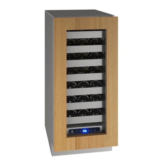
- Page 1 USER GUIDE & SERVICE MANUAL 5 Class UHWC515 15” Wine Captain ® ● ●...
- Page 2 USER GUIDE u-line.com SAFETY • INSTALLATION & INTEGRATION • OPERATING INSTRUCTIONS • MAINTENANCE • SERVICE Contents Service Intro Troubleshooting Safety Wire Diagram Safety and Warning Product Liability Disposal And Recycling Warranty Claims Parts Installation Ordering Replacement Parts Environmental Requirements R600a Specifications...
-
Page 3: Product Information
1. U-Line Customer Care must be contacted immediately at +1.800.779.2547. 2. Service or repairs performed on the unit without prior written approval from U-Line is not permitted. If the unit has been altered or repaired in the field without prior written approval from U-Line, claims will not be eligible. -
Page 4: Safety And Warning
USER GUIDE u-line.com SAFETY • INSTALLATION & INTEGRATION • OPERATING INSTRUCTIONS • MAINTENANCE • SERVICE Safety and Warning NOTICE Please read all instructions before installing, operating, or servicing the appliance. Use this appliance for its intended purpose only and follow... -
Page 5: Disposal And Recycling
USER GUIDE u-line.com Disposal and Recycling DANGER RISK OF CHILD ENTRAPMENT. Before you throw away your old refrigerator or freezer, take off the doors and leave shelves in place so children may not easily climb inside. If the unit is being removed from service for disposal,... -
Page 6: Environmental Requirements
USER GUIDE u-line.com Environmental Requirements This model is intended for indoor/interior applications only and is not to be used in installations that are open/ exposed to natural elements. This unit is designed to operate between 50°F (10°C) and 100°F (38°C). Higher ambient temperatures may reduce the unit’s ability to reach low temperatures and/or reduce... - Page 7 USER GUIDE u-line.com Electrical WARNING SHOCK HAZARD — Electrical Grounding Required. Never attempt to repair or perform maintenance on the unit until the electricity has been disconnected. Never remove the round grounding prong from the plug and never use a two-prong grounding adapter.
-
Page 8: Cutout & Product Dimensions
14 ⁄ ” (379 mm) PREPARE SITE Your U-Line product has been designed for either free- standing or built-in installation. When built-in, your unit does not require additional air space for top, sides, or rear. However, the front grille must NOT be obstructed, 28”... -
Page 9: Side-By-Side Installation
USER GUIDE u-line.com Side-by-Side Installation Hinge-by-Hinge Installation (Mullion) When installing two units hinge-by-hinge, 13/16" (22 mm) OTHER SITE REQUIREMENTS is required for integrated models. Additional space may be Side-by-Side Installation needed for any knobs, pulls or handles installed. Units must operate from separate, properly grounded electrical receptacles placed according to each unit’s... -
Page 10: Anti-Tip Bracket
USER GUIDE u-line.com Anti-Tip Bracket Surrounding area (Top view) Use one of the methods below to secure the unit CABINET/COUNTER ANTI-TIP INSTALLATION (For built-in applications) Back of unit Back wall Slide unit out so screws on front of unit are easily accessible. -
Page 11: General Installation
USER GUIDE u-line.com General Installation INSTALLATION 1. Plug in the power/electrical cord. LEVELING INFORMATION 1. Use a level to 2. Gently push the unit into position. Be careful not to confirm the unit is entangle the cord or water and drain lines, if level. -
Page 12: Integrated Panel Dimensions
USER GUIDE u-line.com Integrated Panel Dimensions Integrated Panel Dimensions Metric measurements rounded and optimized. INTEGRATED PANEL BACK SURFACE MUST HAVE AMPLE FLAT SURFACE TO MOUNT OVERLAY PANEL FLAT AND WITHOUT " INTERFERENCE (20 mm) NOTICE Due to differences in surrounding cabinetry the "... - Page 13 USER GUIDE u-line.com HANDLELESS INTEGRATED DOOR PANEL 3. Prepare the insert(s) that will back up the handleless design. Wooden Insert – Cut 1/8" (3 mm) thick The following procedure is designed to provide a finished, wooden insert(s) to the dimensions below.
- Page 14 USER GUIDE u-line.com Handleless Integrated Panel Dimensions " (3 mm) Top Design " (6 mm) " (22 mm) Ref. " " (R 16 mm) (60 mm) " (379 mm) " (70 mm) Insert Notch " (70 mm) Wooden Insert Notch Depth: "...
- Page 15 USER GUIDE u-line.com EXTENDED INTEGRATED PANEL 3. Optional: Install handles and hardware NOTICE Due to differences in surrounding cabinetry the NOTICE panel may not perfectly align with door. The The door panel must not weigh more than 20 lbs procedure below is designed to provide a (10 kg).
- Page 16 Extended Integrated Panel Dimensions Integrated Grille If you would like to cover the grille with an integrated BACK SURFACE MUST HAVE AMPLE FLAT SURFACE TO MOUNT OVERLAY PANEL FLAT AND WITHOUT panel, purchase U-Line’s adjustable grille accessories. " INTERFERENCE (20 mm) "...
-
Page 17: Integrated Panel Installation
11.Remove clamps from door. panel to door using Clamp clamps. A robust tape may also be NOTICE used. U-Line If panel requires additional adjustment after recommends the removing clamps, slightly loosen each screw and use of bar clamps Door/Drawer adjust panel as necessary. Tighten screws upon to secure the panel completion. -
Page 18: Grille Installation
USER GUIDE u-line.com Grille Installation REMOVING AND INSTALLING GRILLE WARNING Disconnect electric power to the unit before removing the grille. When using the unit, the grille must be installed. WARNING DO NOT touch the condenser fins. The condenser fins are SHARP and can be easily damaged. -
Page 19: Door Swing
USER GUIDE u-line.com Door Swing Wall For Integrated models that are installed adjacent to a wall, 1/2" (13 mm) 1/2" (13 mm) clearance is recommended from wall on hinge side to allow the door to open 90°. Allow for additional space for any knobs or pulls installed on the integrated panel/frame. -
Page 20: Door Alignment And Adjustment
USER GUIDE u-line.com Door Adjustments REVERSING THE DOOR Open door. DOOR ALIGNMENT AND ADJUSTMENT Using T-25 Torx bit loosen screw #1 and remove screw Align and adjust the door if it is not level or not sealing #2 on top and bottom hinge. Slide and remove the properly. -
Page 21: First Use
If the temperature displayed is different than selected, the unit is progressing towards the selected temperature. Time to reach set point varies based upon ambient temperature, temperature of product loaded, door openings, etc. U-Line recommends allowing the unit to reach set points before loading. -
Page 22: Control Operation
USER GUIDE u-line.com Control Operation CONTROL FUNCTION GUIDE FUNCTION COMMAND NOTES ON/OFF Press and release Unit will immediately turn On or OFF When the display is flashing, press Adjust Temperature Press and release adjust the set point temperature. Note: temperature... -
Page 23: Product Loading
Typical Can Bottles and cans come in all shapes and sizes. When (135 mm) (123 mm) (12 oz) determining capacities U-Line uses the following sizes. Combinations of red and white bottles are used in Wine ® Captain Models and Beverage Centers. -
Page 24: Interior Adjustments
USER GUIDE u-line.com Interior Adjustments Once removed, retract the slides. Note: The slides on the rack have a thin coating which All 5 Class models feature side mounted rack supports with is used to block moisture and provide lubrication. Use 19 adjustment positions. - Page 25 USER GUIDE u-line.com Wine Storage Options WINE RACK BOTTLE POSITION Specially designed horizontal wine racks properly position the bottles so the wine remains in contact with the cork, which ensures the cork does not become dry. Racks are designed to accommodate typical 750ml wine bottles as follows: UHWC515 15”...
-
Page 26: Wine Guide
As a general rule, one should aim to ascend in flavor and palate. Do not be afraid to make mistakes. Experiment, quality of wines served. discover, but most of all, enjoy yourself and your new U-Line product. Serve a: Before a: DRY wine... - Page 27 USER GUIDE u-line.com Common Food and Wine Matches The Cork: A Mystery on Its Own Cork Presentation. The ritual of the presentation of the Foods Wines cork has a rich and fascinating history dating back to Fish, Shell Fish, Crab, Oysters...
-
Page 28: Ideal Wine Storage Considerations
USER GUIDE u-line.com Common Tasting Terms IDEAL WINE STORAGE CONSIDERATIONS Temperature: The most important element about Terminology Description storage temperature is stability. If wine is kept in a stable Acidity A critical element of wine that is responsible environment between 40 º... - Page 29 º Sparkling Approximately Wine Captain ® Models - A Touch of Elegance In 1985 U-Line was the first North American appliance manufacturer to develop a residential wine storage unit, the Wine Captain ® . Each U-Line Wine Captain ® model is...
-
Page 30: Interior Cleaning
USER GUIDE u-line.com Cleaning To clean integrated panels, use household cleaner per the cabinet manufacturer’s recommendation. Stainless Models Stainless door panels and handles can discolor when INTERIOR CLEANING exposed to chlorine gas, pool chemicals, saltwater or Disconnect power to the unit. - Page 31 USER GUIDE u-line.com NOTICE The drain pan was not designed to capture the water created when manually defrosting. To prevent water from overflowing the drain pan and possibly damaging water sensitive flooring, the unit must be removed from cabinetry. To defrost: 1.
-
Page 32: Cleaning Condenser
USER GUIDE u-line.com Cleaning Condenser INTERVAL - EVERY SIX MONTHS To maintain operational efficiency, keep the front grille free of dust and lint, and clean the condenser when necessary. Depending on environmental conditions, more or less frequent cleaning may be necessary. -
Page 33: Extended Non-Use
If the unit will be exposed to temperatures of 40°F (5°C) or less, the steps above must be followed. For questions regarding winterization, please call U-Line at 800.779.2547. CAUTION Damage caused by freezing temperatures is not covered by the warranty. -
Page 34: Before Calling For Service
BEFORE CALLING FOR SERVICE • Condenser Fan: Air moving through a condenser may be heard. If you think your U-Line product is malfunctioning, read the CONTROL OPERATION section to clearly understand the • Automatic Defrost Drain Pan: Water may be heard function of the control. -
Page 35: Checking Product Temperature
USER GUIDE u-line.com u-line.com CHECKING PRODUCT TEMPERATURE Causes which affect the internal temperatures of the cabinet include: • Temperature setting. • Ambient temperature where installed. • Installation in direct sunlight or near a heat source. • The number of door openings and the time the door is open. -
Page 36: Wire Diagram
USER GUIDE u-line.com Wire Diagram Wire Diagram... -
Page 37: Product Liability
The part that caused the damage must be returned to U-Line in its entirety. The part must be clearly labeled with the serial number of the unit it was removed from, the date, and the servicer who removed the part. -
Page 38: Warranty Claims
Claims must be submitted online at • Final billing - Remodel www.U-LineService.com Warranty parts will be shipped at no charge after U-Line • 60 day submittal deadline from date of completed confirms warranty status. Please provide the model, serial service number, part number and part description. - Page 39 USER GUIDE u-line.com Parts UHWC515-IS01A ANTI-TIP BRACKET 80-55449-00 BACK PANEL 80-55450-00 COMPRESSOR W/ELECTRICALS 80-55452-00 CONDENSER ASSEMBLY 80-55453-00 CONDENSER FAN MOTOR 80-54014-00 DISPLAY MODULE 80-55429-00 DOOR ASSEMBLY 80-55469-00 DRAIN PAN 80-54217-00 DRIER 80-54055-00 EVAPORATOR ASSEMBLY 80-55458-00 EVAPORATOR COVER 80-55456-00 EVAPORATOR FAN W/COVER...
-
Page 40: Ordering Replacement Parts
Warranty parts will be shipped at no charge after U-Line confirms warranty status. Please provide the model, serial number, part number and part description. Some parts will require color or voltage information. - Page 41 Never use a torch on a fully charged refrigeration system. Never substitute U-Line OEM replacement parts or methods of construction. R-600a must be stored and transported in Technician must observe all federal, state and local laws regarding refrigerants.
- Page 42 USER GUIDE USER GUIDE u-line.com u-line.com SAFETY • INSTALLATION & INTEGRATION • OPERATING INSTRUCTIONS • MAINTENANCE • SERVICE R-600A SPECIFICATIONS/LABELING WARNING R-600a equipped products are labeled (both the unit and the compressor). Only skilled and well trained service technicians permitted to service R-600a equipped products.
-
Page 43: Leak Detection
USER GUIDE USER GUIDE u-line.com u-line.com SAFETY • INSTALLATION & INTEGRATION • OPERATING INSTRUCTIONS • MAINTENANCE • SERVICE Evacuate/reclaim via the piecing pliers to ensure the When re-brazing, the system must be purged with dry system is empty of R-600a before any system work is nitrogen and at least one access point open to the performed. - Page 44 USER GUIDE USER GUIDE u-line.com u-line.com SAFETY • INSTALLATION & INTEGRATION • OPERATING INSTRUCTIONS • MAINTENANCE • SERVICE The low side of the refrigeration system (evaporator, Proper ventilation during service is required. compressor and suction line) must be leak tested with the compressor off (equalized pressure).
-
Page 45: System Diagnosis Guide
USER GUIDE u-line.com System Diagnosis Guide REGRIGERATION SYSTEM DIAGNOSIS GUIDE System Suction Suction Compressor Condenser Capillary Evaporator Wattage Condition Pressure Line Discharge Tube Normal Normal Slightly Very hot Very hot Warm Cold Normal below room temperature Overcharge Higher than Very cold... -
Page 46: Compressor Specifications
USER GUIDE u-line.com Compressor Specifications FMXA9C REFRIGERANT R600A DANGER VOLTAGE 230 VAC FREQUENCY 43-134 Hz START WINDING 20 Ohm at 77 Electrocution can cause death or serious injury. RUN WINDING 20 Ohm at 77 Burns from hot or cold surfaces can cause serious injury. -
Page 47: Troubleshooting - Extended
• Automatic Defrost Drain Pan: Water may be heard U-Line Corp, “Customer Care Facility” at +1.800.779.2547 dripping or running into the drain pan when the unit is for assistance. in the defrost cycle. - Page 48 USER GUIDE u-line.com TROUBLESHOOTING GUIDE Concern Potential Causes Action Not Cooling Compressor overheating Verify proper air flow through condenser. Is condenser clean? Confirm condenser fan operation. Compressor not operating Test overload and relay, replace as needed. Compressor operating - no cooling Refer to System Diagnosis Guide.
-
Page 49: Main Control
USER GUIDE u-line.com MAIN CONTROL CAUTION The main control board is very robust and is rarely the cause of system issues. It is important to fully diagnose Precautions must be taken while working with the board for any suspected failures before attempting live electrical equipment. - Page 50 USER GUIDE u-line.com Control Operation-Service CONTROL FUNCTION GUIDE FUNCTION COMMAND DISPLAY/OPTIONS UI BUTTON LAYOUT and release Unit will immediately Press ON/OFF turn ON or OFF Sabbath Mode See “Sabbath Mode” section Hidden Button SHOWROOM MODE -Access Service Menu This mode is designed to show units in a display -No LED directly above.
-
Page 51: View Error Log
USER GUIDE u-line.com SERVICE MODE GUIDE SERVICE MODE GUIDE 0. Exit THERMISTOR 1 — ZONE 1. Thermistor 1 temperature not including offsets. This shows the pure thermistor reading with no offsets 2. Thermistor 2 temperature not including offsets. taken into account. - Page 52 USER GUIDE u-line.com E3: Thermistor 3 open. MAIN SOFTWARE E4: Thermistor 4 open (Does not apply to this model). 26. Does not apply to this model E5: Thermistor 1 shorted. 27. FACTORY TEST MODEL E6: Thermistor 2 shorted. 0 = Off, 1 = On E7: Thermistor 3 shorted.
-
Page 53: Model List
MODEL NUMBER 1. Disconnect the unit from power source. 2. Push and hold the U-Line button. 3. While still holding the U-Line button, plug the unit into the appropriate power source. 4. When the flashing digits appear (3-5 seconds), use the up and down arrow buttons to select the appropriate model number*. - Page 54 USER GUIDE u-line.com Control Operation-Service...
-
Page 55: Evaporator Thermistor
USER GUIDE u-line.com Thermistors Evaporator Thermistor Thermistors are used for various temperature readings. If the evaporator thermistor fails, the unit will rely on a USER GUIDE Thermistors provide reliable temperature readings preset defrost timer during defrost cycles. The unit will u-line.com... - Page 56 USER GUIDE u-line.com Defrost This unit defrosts every 12 hours of compressor runtime for 45 minutes. If you have verified that the unit does not have an ambient air leak, utilize the Control Operation - Service section and adjust unit to defrost every 9 hours for 60 minutes.
-
Page 57: Remove Fan And Cover
USER GUIDE u-line.com Remove Fan and Cover Remove insulating foam from refrigerant line pass- through hole as needed to gain clearance for fan plug. CONVECTION COOLING Remove internal shelving. This unit is equipped with an advanced convection cooling system. Convection cooling stabilizes cabinet temperature, Remove 8 evaporator cover screws. - Page 58 USER GUIDE u-line.com NOTICE Fan must be oriented to pull air in through lower evaporator cover vents and push air out at fan mounting location. 13. Installation is the reverse of removal. 14. Care must be taken to assure the bottom of the evaporator cover is reinstalled behind the front edge of the train trough.
-
Page 59: One Year Limited Warranty
One Year Limited Warranty For one year from the date of original purchase, this U-Line product warranty covers all parts and labor to repair or replace any part of the product that proves to be defective in materials or workmanship. For products installed and used for normal residential use, material cosmetic defects are included in this warranty, with coverage limited to 60 days from the date of original purchase.
Need help?
Do you have a question about the HWC515IG01A and is the answer not in the manual?
Questions and answers