Table of Contents
Advertisement
Quick Links
Advertisement
Table of Contents

Summary of Contents for Heatrae Sadia HI-MAX STORE
- Page 1 703034483_issue_02 HI-MAX STORE Installation, operation and maintenance manual...
-
Page 3: Table Of Contents
6.2 Safety valve 6.3 Strainer 6.4 Plate heat exchanger 7. Commissioning 7.1 Commissioning district heating system 7.2 Filling the system 7.3 Product installation & service documentation. 8. Service 8.1 General 8.2 Fault finding 9. Spare parts 9.1 Spare parts - HI-MAX STORE... -
Page 4: Introduction
The cylinder frame arrangement permits the cylinder to sit above a washing machine. The HI-MAX STORE HIU is wall mounted and can be supplied with a first fix rail for ease of installation. The unit is supplied complete with all the necessary safety and control devices needed to allow connection to the community heating system and the apartment's central heating and hot water systems. -
Page 5: Liabilities
# DHW - Domestic Hot Water # T&P - Temperature & Pressure relief valve # PRV - Pressure Reducing Valve # Prv - Pressure relief valve # Stv - Safety Tempering Valve # HIU - Heat Interface Unit # PICV - Pressure Independent Control Valve 1.4 Liabilities Manufacturers liability Our products are manufactured in compliance with the requirements of the various applicable... -
Page 6: Recommendations
The combination of pressurisation and hot water could lead to serious physical injury if the safety instructions in this manual are not adhered to. The unit is also designed to work at district heating hydraulic pressures up to 16 bar g and temperatures up to 90°C, which, if exposed to could lead to serious physical injury. -
Page 7: Technical Specifications
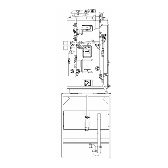
DO NOT bypass the thermal cut-out(s) in any circumstances. WARNING The heat meter can be installed within the space provided inside the HI-MAX STORE HIU. Although most heat meters are now battery powered some are still provided with a mains power supply. - Page 8 Fig 1. Product Features and Components for the HI-MAX STORE HIU page 6 1. First fix rail bracket 2. 4 No. Fixing holes for first fix rail (Ø 7mm) 3. HIU mounting studs (M6) x 2. Supplied with HIU 4. 15mm central heating system safety valve 3 bar g...
-
Page 9: Dimensions And Weight
20. Safety valve discharge pipe Ø15 mm 21. M12 cable gland (2 No.) 22. Actuator Cable Connector block 3.2 Dimensions and Weight Fig 2. HI-MAX STORE HEAT INTERFACE UNIT Unit Dry Weight (kg) Wet Weight (kg) HI-MAX STORE 1st fix rail HI-MAX STORE WITH CASINGS 11.2... -
Page 10: Dimensions And Features
Note: All dimensions are for reference only. page 7 3.3 Dimensions and features - HI-MAX STORE Fig 3. HI-MAX STORE Two heating zone model detailed Cylinder size** 125i 145i 170i 210i 250i 300i Dimension (mm) 2096 2217 2379 1584* 1855* xxxx... -
Page 11: Hydraulic Diagrams
Primary Side Pressure drop 30 kPa page 8 3.4 Hydraulic Diagrams Fig 4. HI-MAX STORE Heat Interface Unit with a Megaflo Systemfit cylinder- One Heating Zone See Page 10 for a legend of symbols page 9 3.5 Hydraulic diagrams legend... -
Page 12: Wiring Diagram
Fig 5. Schematics Table page 10 3.6 Wiring diagram... -
Page 13: Before Installation
I.E.E Electrical Regulations UK Water Regulations 4.2 Installation requirements Limitations The HI-MAX STORE HIU should not be used in association with any of the following: # Situations where maintenance is likely to be neglected or safety devices tampered with. # Water supplies that have either inadequate pressure or where the supply may be intermittent. -
Page 14: Positioning And Access
# Access to associated controls must be available for the servicing and maintenance of the system. # Ensure that the wall that the Heatrae Sadia HI- MAX STORE is mounted on is level and capable of permanently supporting the weight when the unit is full of water. - Page 15 Fig 6. Fitting the first fix rail (Minimum clearance) Fig 7. Minimum Clearances Please note that the clearance dimension detailed above are for guidance. All dimensions are in mm. page 13...
-
Page 16: Installation
5. Installation 5.1 HIU Installation 1. Fix the 1st fix rail to the wall using suitable fixings and ensure the rail is level (Fig. Fig 8. First fix rail mounting details 2. Slide the two studs provided on the 1st fix rail through the slotted holes in the unit back plate and secure loosely with the M6 nuts provided (Fig. - Page 17 Fig 9. HIU mounting details 3. Mark out and drill the bottom fixing points and use suitable fixings for the mounting surface (see Fig 10).
- Page 18 Fig 10. HI-MAX STORE - Bottom Support Fixing Points 4. Fix the casing on by dropping the folds on the casing into the slots on the backplate. Fix with two screws underneath (Fig.12) Fig 11. HI-MAX STORE HIU - Casing mounting Fig 12.
-
Page 19: Cylinder And Frame Installation
DO NOT operate the immersion heaters until the cylinder has been filled with water. page 14 5.2 Cylinder and frame installation 1. Place the frame in final position, ensuring the back of the frame is up against the wall. Secure the frame to the floor and wall using screws through the 8 holes provided. IMPORTANT Ensure when fixing the frame to the floor that the surface is even and level. - Page 20 2. Lift the cylinder on to the frame and push it back to the location ring on the frame cylinder shelf. Take care not to scratch the shelf by tilting the cylinder back. For lifting purposes please take note of the cylinder weight detailed in the cylinder manual and add 5kgs for any ancillary components.
- Page 21 5. Fit the lower safety valve discharge pipe to the upper discharge pipe using the 22mm compression coupling provided. Adjust the cylinder as necessary on the frame. IMPORTANT The safety discharge pipework from an unvented cylinder must be suitable to withstand high temperatures circa 100°C for prolonged periods.
-
Page 22: Cylinder And Hiu Installation
5.3 Cylinder and HIU installation Filling the Cylinder # Ensure the drain cock is CLOSED. # Open a hot tap furthest from the cylinder. # Open the isolating valve on the 3 bar pressure reducing valve by turning the blue handle on the stop cock (if fitted in this position) so that it lies parallel to the direction of flow. -
Page 23: Modesty Panel Installation
# Open the isolating valves at either end of the filling loop and allow to fill from the mains inlet supply. # To ensure the cylinder primary heat exchanger is filled, both of the 2 port motorised valve (supplied) should be manually opened by moving the lever on the motor housing to the MANUAL setting. -
Page 24: Modesty Panel Fitting Instructions
Follow the instructions carefully. It is recommended that the finished installation is checked by a qualified electrician for earth continuity. The provided shakeproof washers are essential to creating earth continuity within the product and MUST be used. Please refer to operation 8 of the fitting instructions on following page. Dimension / Connection 125 2082 2208 2364 1125 1250 1407... - Page 25 4. Using the "C" bracket, secure the back of the side frame with 1 No. M4x35mm screw. 5. Using 1 No. M4x35mm screw and shakeproof washer fix the side panel to the cylinder frame. 6. Using the "C" bracket, secure the back of the side panel with 1 No. M4x35mm screw. 7.
-
Page 26: Components
8. When fixing the front panels ensure that the shakeproof washers are correctly fitted. 9. Using M5x20mm screw, shakeproof washer & plastic cap fit upper front panel. page 18 Components 6.1 District control valve Application # The pressure independent balancing & control valve (PICV) in your unit provides on/ off control with full authority regardless of any fluctuations in the differential pressure of the system. - Page 27 Fig13. PICV PICV makes it simple to achieve 100% control of the water flow in the building, while creating high comfort and energy savings at the same time. # An additional benefit is that no balancing is required if further stages are added to the system, or if the dimensioned capacity is changed.
- Page 28 Fig 15. PICV Installation Benefits # No further regulating valves required in the distribution pipework when PICV is installed at terminals. # Total number of valves minimized due to the 4-in-1 design. # Minimized commissioning time due to automatic balancing of the system. # No minimum straight pipe lengths required before or after the valve.
- Page 29 page 19 PICV Fig 16. Flow Characteristics Pre-set Flow l/h Flow l/s, Flow gpm 0.028 0.44 0.036 0.56 0.043 0.69 0.051 0.81 0.059 0.93 0.067 1.06 0.074 1.18 0.082 1.30 0.090 1.42 0.098 1.55 0.105 1.67 0.113 1.79 0.121 1.92 0.129 2.04 0.136...
-
Page 30: Safety Valve
6.2 Safety valve Safety Valve The HI-MAX STORE HIU is supplied with a sealed system safety valve set to lift at 3.0 bar The safety valve should be checked periodically to ensure that the valve is operational. This is done by simply twisting the red plastic cap at the top of the valve. In doing so, a small burst of water will discharge from the valve, which can be witnessed through a tundish. - Page 31 Fig 19 Y Strainer Y Strainer Installed in the district heating flow pipe, the Y pattern strainer is fitted with a 500 micron filter to prevent any debris from entering the HI-MAX STORE HIU from the district heating system. This filter can be accessed for cleaning purposes through the service plug.
-
Page 32: Plate Heat Exchanger
page 21 6.4 Plate heat exchanger Brazed plate heat exchanger The brazed plate heat exchanger supplied within the heat interface unit provides a break between the primary (community / district) heating circuit and the secondary (apartment) central heating circuit. This is particularly useful in high rise apartment blocks where the primary circuit can run at high pressures. -
Page 33: Commissioning
Fig 21. Position of plate heat exchanger page 22 7.0 Commissioning 7.1 Commissioning the district heating system 1. Depending on the size of the building there will be an element of diversification factored into the design. As such the centralised plant and pumps are unlikely to be able to supply 100% of the heat load to all apartments at any one time. -
Page 34: Product Installation & Service Documentation
Note the PICV will take a few minutes to close. Fig 22. Setting the flow rate dial page 23 7.3 Product installation & service documentation HEAT INTERFACE UNIT COMMISSIONING CHECKLIST This commissioning checklist is to be completed in full by the competent person who commissioned the HIU as a means of demonstrating how the unit was installed and commissioned and must be handed to the customer to keep for future reference. - Page 35 page 24 HEAT INTERFACE UNIT COMMISSIONING CHECKLIST (continued)
- Page 36 page 25...
-
Page 37: Service
8.0 Service 8.1 General Check and clean strainer filter The strainer filter is accessed through the strainer service plug as detailed in Fig 24. 1. Isolate the electrical supply. 2. Using the isolation valves shut off the district heating flow and return connections as detailed in Fig 23. - Page 38 Fig 24. Strainer service plug 4. Remove the strainer filter and clean under a cold water tap. 5. Replace filter, refit service plug, open up the district isolation valves and switch electrical power back on. Check the inhibitor content in the apartment's central heating system 1.
- Page 39 STORE HIU to be isolated from the district heating system during flushing and filling of the distribution network. District heating piping arrangement: Where the HI-MAX STORE HIU is fitted with a two port on/off district heating control valve, all branches within the distribution pipework should be fitted with a reduced flow bypass valve to ensure water flows through these pipes at all times.
-
Page 40: Fault Finding
Remove and clean filter. Strainer blocked. Ensure all isolation valves are open. Isolation valves in closed position. Ensure HI-MAX STORE unit is correctly piped. Incorrectly piped. No hot water Programmer incorrectly set, faulty, or Check programmer settings, wiring, and is wired incorrectly. -
Page 41: Spare Parts
Isolation valves in closed position. Ensure all isolation valves are open. Incorrectly piped. Ensure HI-MAX STORE unit is correctly piped. Insufficient heat Low district heating flow temperature. Check district flow pipe temperature / heat meter Low district heating flow rate. - Page 42 Please note for all other spare parts associated with the Megaflo eco Systemfit cylinder, refer to the spare parts section of the Megaflo Eco Systemfit Cylinder manual. page 29...
- Page 43 9.2 Spare Parts - HI-MAX STORE HIU Item Description Part Number Safety valve - 15mm - 3 bar 40405000 Isolation valve 3/4"# bsp male/male (blue) 5136203 Isolation valve 3/4"# bsp male/male (red) 5136204 Actuator - on/off - 230V 24500024 Strainer - 3/4"# bsp male/male 24500020 Binder test points - 1/4"# bsp (pack of 2)
- Page 44 Heatrae Sadia package are covered by their individual respective warranties In short; # The HI-MAX STORE HIU is covered for a two year parts and labour warranty # The Megaflo Cylinder is covered by the Megaflo Lifetime warranty - full details of which are available in the Megaflo Cylinder fitting instructions.
- Page 45 Vale Park, Evesham Worcs, WR11 1GS Tel: 01386 760066 Fax: 01386 760077 Electric Water Heating Co 2 Horsecroft Place, Pinnacles, Harlow, Essex, CM19 5BT Tel: 0845 055 3811 Email: sales@ewh.co.uk Units 9 & 10 Hexagon Business Centre Springfield Road, Hayes, Middlesex, UB4 0TY Tel: 020 8606 3567...
- Page 46 William Wilson Ltd Unit 3A, 780 South Street, Whiteinch, Glasgow, G14 0SY Tel: 0141 434 1530 Alternatively contact your local supplying merchant or wholesale branch. 7034483_issue_02 page 32 4483_issue_02...
Need help?
Do you have a question about the HI-MAX STORE and is the answer not in the manual?
Questions and answers