schmersal RSS 36-D 10M Manual
Hide thumbs
Also See for RSS 36-D 10M:
- Manual (24 pages) ,
- Operation – and assembly instruction (24 pages)

Subscribe to Our Youtube Channel
Related Manuals for schmersal RSS 36-D 10M


Summary of Contents for schmersal RSS 36-D 10M
-
Page 1: Table Of Contents
7.3 Operating principle of the electronic diagnostic output 7.4 Safety-sensors with serial diagnostic function 8 Set-up and maintenance 9 Disassembly and disposal 9.1 Disassembly 9.2 Disposal 1 About this document The Schmersal range of products is not intended for private consumers. 1.1 Function 1-23... -
Page 2: Target Group Of The Operating Instructions: Authorised Qualified Personnel
Warning:Failure to comply with this warning notice could lead to physical injury and/or damage to the machine. 1.4 Appropriate use The Schmersal range of products is not intended for private consumers. The products described in these operating instructions are developed to execute safety-related functions as part of an entire plant or machine. -
Page 3: Product Description
Further technical information can be found in the Schmersal catalogues or in the online catalogue on the Internet: products.schmersal.com. 2 Product description 2.1 Ordering code Produkt-typebetegnelse: RSS 36 (1)-(2)-(3)-(4) uten standard kodet individuelt kodet individuelt kodet, kan innlæres på nytt... -
Page 4: Warning About Misuse
The safety function consists of safely switching off the safety outputs when the safety guard is opened and maintaining the safe switched off condition of the safety outputs for as long as the safety guard is open. The safety switchgears are classified according to ISO 14119 as type 4 interlocking devices. Designs with individual coding are classified as highly coded. - Page 5 Standard EN ISO 13849-1 EN IEC 60947-5-3 EN IEC 61508 Generell informasjon Universell koding Coding level according to EN ISO 14119 Aktivt prinsipp RFID Frequency band RFID 125 kHz Transmitter output RFID, maximum -6 dB/m Huskonstruksjonsform Blokk Installasjonsbetingelser (mekaniske) ikke i flukt Sensortopologi Sensor for seriekabling Kapslingsmateriale...
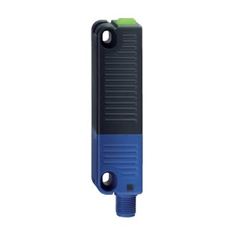
- Page 6 Mission time 20 år Mekaniske data Nøkkelinnganger på side Aktivt område på side Mekanisk levetid, minimum 1 000 000 bevegelser Note (Mechanical life) Aktueringshastighet 0,25 m/s Operasjoner for vakter ≤ 5 kg Hysterese, (bryterdistanse), maksimum 2 mm Gjenta nøyaktighet R 0,5 mm Merk (Gjentagelsesnøyaktighet R) Den lange siden tillater en maksimal feiljustering av høyden (x) for...
- Page 7 Bredde på sensor 106,3 mm Høyde på sensor 25 mm Omgivelsesbetingelser Tetthetsgrad IP65 IP67 IP69 Ambient temperature -25 ... +70 °C Lagrings- og transporttemparatur, minimum -25 °C Lagrings- og transporttemparatur, maksimum +85 °C Temperaturstabilitet for materialet i kabelen (i bevegelse), -10 °C minimum Temperaturstabilitet for materialet i kabelen (i hvileposisjon),...
- Page 8 Designation, Safety inputs X1 and X2 Current consumption of the safety inputs 5 mA Test pulse duration, maximum 1 ms Test pulse interval, minimum 100 ms Classification ZVEI CB24I, Sink Classification ZVEI CB24I, Source Electrical data - Safety digital outputs Designation, Safety outputs Y1 and Y2 Driftssstrøm (sikkerhetsutganger)
- Page 9 This device complies with the nerve stimulation limits (ISED CNR-102) when operated at a minimum distance of 100 In the event of changes or modifications that have not been expressly approved by K.A. Schmersal GmbH & Co. KG, the user's authorisation to use the device may become ineffective.
-
Page 10: Mounting
4 Mounting 4.1 General mounting instructions Please observe the relevant requirements of the standards ISO 12100, ISO 14119 and ISO 14120. Ensure the safety sensor and actuator is mounted on a flat surface. The component can be mounted in any position. The universal mounting holes provide for a variable mounting by means of M4 screws. -
Page 11: Accessories
Alternative suitable actuators with different design: refer to products.schmersal.com. 4.3 Accessories Set of disposable screws (order separately) - 4x M4x25 incl. washers, order number 101217746 - 4x M4x30 incl. washers, Bestellnummer 101217747 Sealing kit (order separately) - Order number 101215048 - 8 plugs and 4 under seals - To seal the mounting holes and as a spacer (approx. -
Page 12: Switch Distance
4.4 Switch distance Switching distances in mm to IEC 60947-5-3 Typical switching distance s Assured switching distance s Assured switch-off distance s There are new switch distances as per the table below owing to the necessity of technical modifications (V2). Please check the design of your guard system following installation to ensure adherence to the secured switch distances (≤... -
Page 13: Adjustment
The side allows for a maximum height misalignment (X) of sensor and actuator of ± 8 mm (e.g. mounting tolerance or due to guard door sagging). The axial misalignment (y) is max. ± 18 mm. Latching versions X ± 5 mm, Y ± 3 mm. The latching force will be reduced by misalignment. -
Page 14: Serial Diagnostic -Sd
Requirements for the connected safety-monitoring module: dual-channel safety input, suitable for p-type sensors with NO function Information for the selection of suitable safety-monitoring modules can be found in the Schmersal catalogues or in the online catalogue on the Internet: products.schmersal.com. -
Page 15: Wiring Examples For Series-Wiring
5.3 Wiring examples for series-wiring Series-wiring can be set up. In the case of a series connection, the risk time remains unchanged and the reaction time increases by the sum of the reaction time of the inputs per additional unit specified in the technical data. The number of components is only limited by the external cable protection according to the technical data and the line loss. - Page 16 Function safety switchgear Pin configuration of the Colour codes of the Schmersal Poss. connector connectors colour codes of other customary connectors 8-pin 5-pin 8-pin version ST 5-pin to IEC version ST version ST version ST 60947-5-2: 2007 with...
-
Page 17: Actuator Coding
Connecting cables (PUR) with coupling (female) IP67 / IP69, M12, 5-pole - 5 x 0.34 mm² to EN 60947-5-2 Cable length Ordering code 5.0 m 103010816 10.0 m 103010818 15.0 m 103010820 6 Actuator coding Safety sensors with standard coding are ready to use upon delivery. Individually coded safety sensors and actuators will require the following "teach-in"... -
Page 18: Operating Principle Of The Electronic Diagnostic Output
The green LED indicates that the safety sensor is ready for operation. The supply voltage is on and all safety inputs are present. Flashing (1Hz) of the green LED signals that a voltage is missing on one or both of the safety inputs (X1 and/or X2). The yellow LED always signals the presence of an actuator within range. -
Page 19: Safety-Sensors With Serial Diagnostic Function
Table 1: Examples of the diagnostic function of the safety-sensor with conventional diagnostic output Sensor function LED's Diagnostic- Safety Comments output outputs green yellow Y1, Y2 Supply voltage Voltage on, no evaluation of the voltage quality actuated 24 V 24 V The yellow LED always... - Page 20 SD-Gateway is integrated as a slave in an existing field bus system. In this way, the diagnostic signals can be evaluated by means of a PLC. The necessary software for the integration of the SD-Gateway is available for download at products.schmersal.com. The response data and the diagnostic data are automatically and permanently written in the assigned input byte of the PLC for each safety sensor in the series-wired chain.
- Page 21 Table 2: Function of the visual diagnostic LEDs, the serial status signals and the safety outputs by means of an example System LED's Safety Status signals serial diagnostic byte Bit n° conditi output green yellow Y1, Y2 Non- actaute inputs X1 and enabled Actuate...
-
Page 22: Set-Up And Maintenance
Table 3: Tabular overview of status signals, warnings or error messages(The described condition is reached, when Bit = Communication Request byte: from the PLC to the local safety sensor directions: Response byte: from the local safety sensor to the PLC ... -
Page 23: Disassembly
23-23 Schmersal Nordiska AB, F O Petersons gata 28, S-421 31 Västra Frölunda Data og verdier er kontrollert omhyggelig. Bilder kan avvike fra originalen. Ytterligere tekniske data finner du i manualen. Tekniske modifiseringer og feil kan forkomme. Generert til 11.06.2023, 16:53...
Need help?
Do you have a question about the RSS 36-D 10M and is the answer not in the manual?
Questions and answers