Advertisement
Quick Links
The FIF-12 is the USB 2.0 Interface Unit which allows cloning of channel data to Vertex Standard transceivers
re-writing of the firmware on some Vertex Standard transceivers
o
S
peraTing
ySTem
Microsoft
Windows
2000,
®
®
Windows
XP (32 bit Version only),
®
Windows
Vista (32 / 64 bit Version),
®
Windows
7 (32 / 64 bit Version), or
®
Windows
8 (32 / 64 bit Version)
®
p
l
acking
iST
FIF-12 Interface Unit
USB Cable
CD-ROM (Includes the Driver File and Operating Manual)
o
peraTion
Log on to the computer using the "Administrator"
account. If you do not know how to change the ac-
count to "Administrator," please consult your computer
system administrator.
Install the FIF-12 driver.
When the driver installation is finished, connect the
supplied USB Cable between the FIF-12 and your com-
puter, then connect the appropriate Connection Cable
(option) between the FIF-12 and the transceiver.
Confirm the computer's communication port which
detects the FIF-12.
Execute the cloning/writing software.
If this is the first time you have executed the program-
ming/writing software on this computer after installing
the FIF-12 USB Interface, check the programming/
writing software's "CONFIGURE" parameter, to be sure
that the communication port of the programming/writ-
ing software matches that set for the FIF-12. See page
16 for details.
o
c
pTional
onnecTion
CT-104A
Connection Cable with 8-pin Modular Jack
(for the VX-2100/-2200/-4500/-4600/-7100/-7200,
EVX-5300/-5400, VXR-1000/-7000/-9000 etc)
CT-105 Connection Cable with 14-pin Universal Connector
(for the VX-537/-5500/-6000 etc)
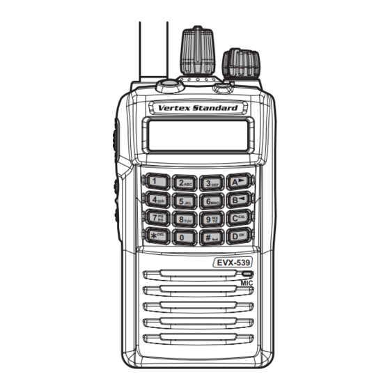
CT-106 Connection Cable 4-conductor Mini-phone Jack
(for the VX-230/-350/-420/-450, EVX-530 etc)
CT-108 Connection Cable with 14-pin Universal Connector
(for the VX-820/-920 etc.)
CT-171 Connection Cable for the FRB-6 Tuning Interface Box
EAJ23X103
fif-12 uSB p
r
equiremenTS
c
aBle
Vertex Standard LMR, Inc.
i
rogramming
nTerface
, using the USB port of a personal computer.
: Check with your Vertex Standard Dealer for applicable models.
The FIF-12 is designed to be connected directly
to the computer's USB port. Devices that are
made to convert a USB device to a 9 pin serial
port will not work and/or may damage the FIF-12.
Connect the Transceiver to this jack using
the appropriate (optional) Connection Cable.
RADIO
ACTIVE
USB PROGRAMMING
INTERFACE
Connect your Computer to this jack
using the supplied USB Cable.
1
A
2
3
ABC
DEF
4
B
5
6
GHI
JKL
MNO
7
PQ
C
CXL
8
9
WX
RS
TUV
YZ
?
DEL
D
OK
0
#
EVX-539
EVX-539
~ 1 ~
NOTE
Status Indicator
GREEN:
Normal Condition
RED:
Uploading/Downloading
ORANGE: Firmware Writing
RADIO
ACTIVE
FIF-12
USB PROGRAMMING
INTERFACE
USB Cable
T
S
fif-12
ypical
eTup for The
, and/or
Personal Computer
Advertisement

Summary of Contents for Vertex Standard FIF-12
- Page 1 The FIF-12 is the USB 2.0 Interface Unit which allows cloning of channel data to Vertex Standard transceivers , and/or re-writing of the firmware on some Vertex Standard transceivers , using the USB port of a personal computer.
- Page 2 4. Click the left mouse button on the “Finish” button. 2. The following window (Install Shield Wizard) will be open. Click the left mouse button on “Next >” button. 5. Connect the FIF-12 to the USB port on your computer, the Driver is recognized automatically. ~ 2 ~...
- Page 3 The river ( Microsoft 2000 ) Windows ® ® 6. Click the left mouse button on the “Finish” button. ~ 3 ~...
- Page 4 “Device Man- on the “Properties” item to open the “System Prop- ager” button to open the “Device Manager” window. erties” window. 3. Confirm the computer’s communication port which de- tects the FIF-12. ~ 4 ~...
- Page 5 4. Click the left mouse button on the “Finish” button. 2. The following window (Install Shield Wizard) will be open. Click the left mouse button on “Next >” button. 5. Connect the FIF-12 to the USB port on your computer. The Driver is recognized automatically. ê...
- Page 6 “Device Man- item. Click the left mouse button on “Properties” to ager” button to open the “Device Manager” window. open the “System Properties” window. 3. Confirm the computer’s communication port which de- tects the FIF-12. ~ 6 ~...
- Page 7 ® Note: Please perform this operation after changing user account to an “Administrator”. DO NOT INSTALL ANY HARDWARE BEFORE INSTALLING FIF-12 DRIVER. 1. Set the supplied CD into your CD-ROM drive, then 4. The following window (Install Shield Wizard) will be click the left mouse button on the “setup.exe”.
- Page 8 The river ( Microsoft Vista ) Windows ® ® 7. Connect the FIF-12 to the USB port on your computer, the Driver is recognized automatically. ~ 8 ~...
- Page 9 Click the left mouse button on “Properties” to open the “System Properties” window. 4. Confirm the computer’s communication port which de- tects the FIF-12. 2. Click the left mouse button on the “Device Manager” Item to open the “User Account Control” window.
- Page 10 ® Note: Please perform this operation after changing user account to an “Administrator”. DO NOT INSTALL ANY HARDWARE BEFORE INSTALLING FIF-12 DRIVER. 1. Set the supplied CD into your CD-ROM drive, then 4. The following window (Install Shield Wizard) will be click the left mouse button on the “setup.exe”.
- Page 11 The river ( Microsoft Windows ® ® 7. Connect the FIF-12 to the USB port on your computer, the Driver is recognized automatically. ~ 11 ~...
- Page 12 1. Click the left mouse button on the “start” button, then 3. Confirm the computer’s communication port which de- click the right mouse button on the “Computer” Item. tects the FIF-12. Click the left mouse button on “Properties” to open the “System Properties” window.
- Page 13 ® Note: Please perform this operation after changing user account to an “Administrator”. DO NOT INSTALL ANY HARDWARE BEFORE INSTALLING FIF-12 DRIVER. 1. Set the supplied CD into your CD-ROM drive, then 4. The following window (Install Shield Wizard) will be click the left mouse button on the “setup.exe”.
- Page 14 The river ( Microsoft Windows ® ® 7. Connect the FIF-12 to the USB port on your computer, the Driver is recognized automatically. The “Hardware” icon will appear briefly at the Task Bar. ~ 14 ~...
- Page 15 Item, to open the “Device Manager” window. 2. Click the right mouse button on the “Computer” Item, 4. Confirm the computer’s communication port which de- then click the left mouse button on “Properties” to tects the FIF-12. open the “System Properties” window. ~ 15 ~...
- Page 16 5. Click the left mouse button on the “OK” button. 2. Click the left mouse button on the “Configure” item to open the “Configure” window. 3. Select the communication port which is detecting the FIF-12. ~ 16 ~...
Need help?
Do you have a question about the FIF-12 and is the answer not in the manual?
Questions and answers