
Subscribe to Our Youtube Channel
Related Manuals for ASROCK Z690 Taichi


Summary of Contents for ASROCK Z690 Taichi
- Page 1 Questo manuale d’istruzione è fornito da trovaprezzi.it. Scopri tutte le offerte per AsRock Z690 Taichi cerca il tuo prodotto tra le migliori offerte di Schede Madri...
- Page 2 (including damages for loss of profits, loss of business, loss of data, interruption of business and the like), even if ASRock has been advised of the possibility of such damages arising from any defect or error in the documentation or product.
- Page 3 If you require assistance please call ASRock Tel : +886-2-28965588 ext.123 (Standard International call charges apply) The terms HDMI®...
- Page 4 ES OF ANY KIND WHETHER UNDER THIS AGREEMENT OR OTHERWISE, EVEN IF INTEL HAS BEEN ADVISED OF THE POSSIBILITY OF SUCH DAMAGES. LICENSE TO USE COMMENTS AND SUGGESTIONS. This Agreement does NOT obligate Licensee to provide Intel with comments or suggestions regarding the Software. However, if Licensee provides Intel with comments or suggestions for the modification, correction, improvement or enhancement of (a) the Software or (b) Intel products or processes that work with the Software, Licensee grants to Intel a non-exclusive, worldwide,...
- Page 5 CE Warning This device complies with directive 2014/53/EU issued by the Commision of the European Community. This equipment complies with EU radiation exposure limits set forth for an uncontrolled environment. This equipment should be installed and operated with minimum distance 20cm between the radiator &...
-
Page 6: Table Of Contents
Contents Chapter 1 Introduction Package Contents Specifications Motherboard Layout I/O Panel 802.11ax Wi-Fi 6E Module and ASRock WiFi 2.4/5/6 GHz Antenna Graphics Card Holder 3010 Cooling Fan with Bracket 4010 Cooling Fan Bracket Wireless Dongle USB Bracket Chapter 2 Installation... - Page 7 M.2_SSD (NGFF) Module Installation Guide (M2_3) Chapter 3 Software and Utilities Operation Installing Drivers ASRock Motherboard Utility (A-Tuning) 3.2.1 Installing ASRock Motherboard Utility (A-Tuning) 3.2.2 Using ASRock Motherboard Utility (A-Tuning) ASRock Live Update & APP Shop 3.3.1 UI Overview 3.3.2 Apps 3.3.3 BIOS &...
- Page 8 Advanced Screen 4.6.1 CPU Configuration 4.6.2 Chipset Configuration 4.6.3 Storage Configuration 4.6.4 Intel(R) Thunderbolt 4.6.5 ACPI Configuration 4.6.6 USB Configuration 4.6.7 Trusted Computing Tools Hardware Health Event Monitoring Screen Security Screen 4.10 Boot Screen 4.11 Exit Screen...
-
Page 9: Chapter 1 Introduction
If you require technical support related to this mother- board, please visit our website for specific information about the model you are using. You may find the latest VGA cards and CPU support list on ASRock’s website as well. ASRock website http://www.asrock.com. -
Page 10: Specifications
• Supports DDR5 non-ECC, un-buffered memory up to 6400+(OC)* * Supports DDR5 4400 (1DPC) / 3600 (2DPC) natively. * Please refer to Memory Support List on ASRock's website for more information. (http://www.asrock.com/) • Max. capacity of system memory: 128GB • Supports Intel® Extreme Memory Profile (XMP) 3.0 • 15μ... - Page 11 Z690 Taichi Graphics • Intel® UHD Graphics Built-in Visuals and the VGA outputs can be supported only with processors which are GPU integrated. • Intel® X Graphics Architecture (Gen 12) • Three graphics output options: 1 x HDMI and 2 x Intel®...
- Page 12 1 x Gigabit LAN 10/100/1000 Mb/s (Intel® I219V) • Supports Wake-On-LAN • Supports Lightning/ESD Protection • Supports Energy Efficient Ethernet 802.3az • Supports PXE Wireless • 802.11ax Wi-Fi 6E Module • Supports IEEE 802.11a/b/g/n/ax • Supports Dual-Band 2x2 160MHz with extended 6GHz band* support * Wi-Fi 6E (6GHz band) will be supported by Microsoft®...
- Page 13 Technology (M2_2 and M2_3 only) * Supports Intel® Volume Management Device (VMD) * Supports NVMe SSD as boot disks * Supports ASRock U.2 Kit RAID • Supports RAID 0, RAID 1, RAID 5 and RAID 10 for SATA storage devices • Supports RAID 0, RAID 1 and RAID 5 for M.2 NVMe...
- Page 14 • 2 x CPU/Water Pump Fan Connectors (4-pin) (Smart Fan Speed Control) * CPU_FAN2/WP_3A supports the water cooler fan of maxi- mum 3A (36W) fan power. * CPU_FAN3/WP supports the water cooler fan of maximum 2A (24W) fan power. • 4 x Chassis/Water Pump Fan Connectors (4-pin) (Smart Fan Speed Control) * The Chassis/Water Pump Fan supports the water cooler fan of maximum 2A (24W) fan power.
- Page 15 • ErP/EuP ready (ErP/EuP ready power supply is required) • CEC Tier II ready * For detailed product information, please visit our website: http://www.asrock.com Please realize that there is a certain risk involved with overclocking, including adjusting the setting in the BIOS, applying Untied Overclocking Technology, or using third-party overclocking tools.
-
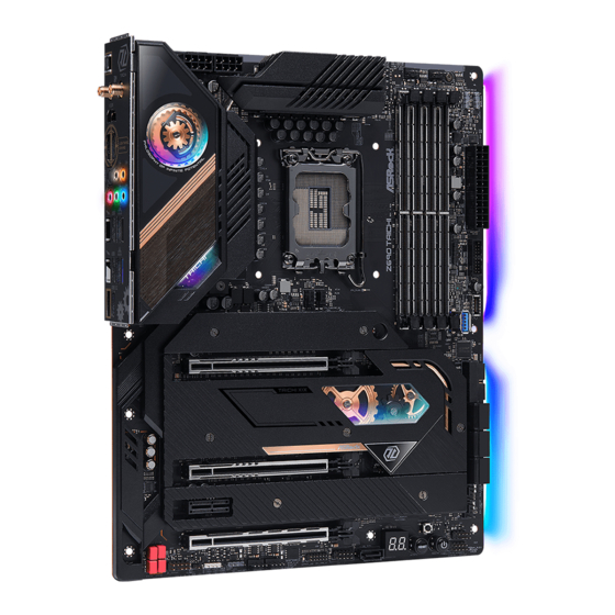
Page 16: Motherboard Layout
1.3 Motherboard Layout VRM_FAN1/WP CPU_FAN3/WP BIOS _FB1 ATX12V1 ATX12V2 H D M I1 Top: TB_1 RJ-45 (I219V) Top: 2.5GLAN TB_2 (Killer® E3100G) CPU_FAN2 CPU_FAN1 /WP_3A F_USB32_TC_1 USB 3.2 Gen2 T: USB3_5 B: USB3_6 CT11 P C I E1 Intel WiFi-802.11ax Module Z690 CT22... - Page 17 Z690 Taichi No. Description 8 pin 12V Power Connector (ATX12V1) 8 pin 12V Power Connector (ATX12V2) 2 x 288-pin DDR5 DIMM Slots (DDR5_A1, DDR5_B1) VRM/Water Pump Fan Connector (VRM_FAN1/WP) 2 x 288-pin DDR5 DIMM Slots (DDR5_A2, DDR5_B2) CPU/Water Pump Fan Connector (CPU_FAN3/WP)
-
Page 18: I/O Panel
1.4 I/O Panel No. Description No. Description Central / Bass (Orange) USB 3.2 Gen1 Type-A Port Rear Speaker (Black) (USB3_3)**** Line In (Light Blue) USB 4.0 Thunderbolt Front Speaker (Lime)* Type-C Port (TB_1) LAN RJ-45 Port (Intel® I219V)** Microphone (Pink) 2.5G LAN RJ-45 Port Optical SPDIF Out Port (Killer®... - Page 19 Z690 Taichi * If you use a 2-channel speaker, please connect the speaker’s plug into “Front Speaker Jack”. See the table below for connection details in accordance with the type of speaker you use. Audio Output Front Speaker Rear Speaker...
-
Page 20: Ax Wi-Fi 6E Module And Asrock Wifi 2.4/5/6 Ghz Antenna
1.5 802.11ax Wi-Fi 6E Module and ASRock WiFi 2.4/5/6 GHz Antenna 802.11ax Wi-Fi 6E + BT Module This motherboard comes with an exclusive 802.11 a/b/g/n/ax Wi-Fi 6E + BT module that offers support for 802.11 a/b/g/n/ax Wi-Fi 6E connectivity standards and Bluetooth. -
Page 21: Graphics Card Holder
Z690 Taichi 1.6 Graphics Card Holder Installing the Graphics Card Holder Before installing the Graphics Card Holder , please make sure that your motherboard is properly installed into a PC case. Step 1 Secure the Graphics Card Holder to the chassis with 2 screws. -
Page 22: 3010 Cooling Fan With Bracket
1.7 3010 Cooling Fan with Bracket Before installing the cooling fan, please make sure that your motherboard is properly installed into a PC case. Installing the 3010 Cooling Fan with Bracket Step 1 Place the 3010 Cooling Fan with Bracket to your motherboard with screw holes aligned. -
Page 23: 4010 Cooling Fan Bracket
Z690 Taichi 1.8 4010 Cooling Fan Bracket Before installing the cooling fan, please make sure that your motherboard is properly installed into a PC case. Installing the 4010 Cooling Fan Bracket Step 1 Attach your 4010 fan to the bracket and secure it with 4 screws. -
Page 24: Wireless Dongle Usb Bracket
1.9 Wireless Dongle USB Bracket Installing the Wireless Dongle USB Bracket Step 1 Plug the Wireless Dongle USB Bracket into the USB 2.0 header on your motherboard. Step 2 Now you have two external USB 2.0 ports at hand. *We recommend you plugging wireless devices dongle into these USB 2.0 ports for the best wireless signal quality. -
Page 25: Chapter 2 Installation
Z690 Taichi Chapter 2 Installation This is an ATX form factor motherboard. Before you install the motherboard, study the configuration of your chassis to ensure that the motherboard fits into it. Pre-installation Precautions Take note of the following precautions before you install motherboard components or change any motherboard settings. -
Page 26: Installing The Cpu
2.1 Installing the CPU 1. Before you insert the 1700-Pin CPU into the socket, please check if the PnP cap is on the socket, if the CPU surface is unclean, or if there are any bent pins in the socket. Do not force to insert the CPU into the socket if above situation is found. - Page 27 Z690 Taichi...
- Page 28 Please save and replace the cover if the processor is removed. The cover must be placed if you wish to return the motherboard for after service.
-
Page 29: Installing The Cpu Fan And Heatsink
Z690 Taichi 2.2 Installing the CPU Fan and Heatsink... -
Page 30: Installing Memory Modules (Dimm)
2.3 Installing Memory Modules (DIMM) This motherboard provides four 288-pin DDR5 (Double Data Rate 5) DIMM slots, and supports Dual Channel Memory Technology. 1. For dual channel configuration, you always need to install identical (the same brand, speed, size and chip-type) DDR5 DIMM pairs. 2. - Page 31 Z690 Taichi...
-
Page 32: Expansion Slots (Pcie Slots)
2.4 Expansion Slots (PCIe Slots) There are 4 PCI Express slots on the motherboard. Before installing an expansion card, please make sure that the power supply is switched off or the power cord is unplugged. Please read the documentation of the expansion card and make necessary hardware settings for the card before you start the installation. -
Page 33: Jumpers Setup
Z690 Taichi 2.5 Jumpers Setup The illustration shows how jumpers are setup. When the jumper cap is placed on the pins, the jumper is “Short”. If no jumper cap is placed on the pins, the jumper is “Open”. Clear CMOS Jumper... -
Page 34: Onboard Headers And Connectors
2.6 Onboard Headers and Connectors Onboard headers and connectors are NOT jumpers. Do NOT place jumper caps over these headers and connectors. Placing jumper caps over the headers and connectors will cause permanent damage to the motherboard. System Panel Header Connect the power PLED+ PLED-... - Page 35 Z690 Taichi Serial ATA3 Connectors These six SATA3 Right Angle: connectors support SATA (SATA3_1: data cables for internal see p.8, No. 15)(Upper) storage devices with up to (SATA3_2: 6.0 Gb/s data transfer rate. see p.8, No. 15)(Lower) (SATA3_3 see p.8, No. 16)(Upper) (SATA3_4: see p.8, No.
- Page 36 USB 3.2 Gen1 Headers There are two headers on Right Angle: this motherboard. Each Dummy IntA_PA_D+ (19-pin USB3_7_8) IntA_PB_D+ IntA_PA_D- USB 3.2 Gen1 header can IntA_PB_D- (see p.8, No. 14) support two ports. IntA_PA_SSTX+ IntA_PB_SSTX+ IntA_PA_SSTX- IntA_PB_SSTX- IntA_PA_SSRX+ IntA_PB_SSRX+ IntA_PA_SSRX- IntA_PB_SSRX- Vbus Vbus...
- Page 37 Z690 Taichi Chassis/Water Pump Fan This motherboard Connectors provides four 4-Pin water (4-pin CHA_FAN1/WP) cooling chassis fan FAN_VOLTAGE (see p.8, No. 18) connectors. If you plan to CHA_FAN_SPEED FAN_SPEED_CONTROL (4-pin CHA_FAN2/WP) connect a 3-Pin chassis (see p.8, No. 19) water cooler fan, please connect it to Pin 1-3.
- Page 38 ATX Power Connector This motherboard pro- (24-pin ATXPWR1) vides a 24-pin ATX power (see p.8, No. 9) connector. To use a 20-pin ATX power supply, please plug it along Pin 1 and Pin ATX 12V Power This motherboard Connectors provides two 8-pin ATX (8-pin ATX12V1) 12V power connectors.
- Page 39 Z690 Taichi RGB LED Header This RGB header is used to (4-pin RGB_LED1) connect RGB LED extension +12V G R (see p.8, No. 31) cable which allow users to choose from various LED lighting effects. Caution: Never install the RGB LED cable in the wrong orientation;...
-
Page 40: Smart Switches
2.7 Smart Switches The motherboard has four smart switches: Power Button, Reset Button, Clear CMOS Buttons and BIOS Flashback Button, allowing users to quickly turn on/off the system, reset the system, clear the CMOS values or flash the BIOS. Power Button Power Button allows users (PWRBTN1) to quickly turn on/off the... - Page 41 (BIOS_FB1) to flash the BIOS. (see p.10, No. 17) ASRock BIOS Flashback feature allows you to update BIOS without powering on the system, even without CPU. Before using the BIOS Flashback function, please suspend BitLocker and any encryption or security relying on the TPM. Make sure that you have already stored and backup-ed the recovery key.
-
Page 42: Dr. Debug
2.8 Dr. Debug Dr. Debug is used to provide code information, which makes troubleshooting even easier. Please see the diagrams below for reading the Dr. Debug codes. Code Description 0x10 PEI_CORE_STARTED 0x11 PEI_CAR_CPU_INIT 0x15 PEI_CAR_NB_INIT 0x19 PEI_CAR_SB_INIT 0x31 PEI_MEMORY_INSTALLED 0x32 PEI_CPU_INIT 0x33 PEI_CPU_CACHE_INIT... - Page 43 Z690 Taichi 0x63 DXE_CPU_INIT 0x68 DXE_NB_HB_INIT 0x69 DXE_NB_INIT 0x6A DXE_NB_SMM_INIT 0x70 DXE_SB_INIT 0x71 DXE_SB_SMM_INIT 0x72 DXE_SB_DEVICES_INIT 0x78 DXE_ACPI_INIT 0x79 DXE_CSM_INIT 0x90 DXE_BDS_STARTED 0x91 DXE_BDS_CONNECT_DRIVERS 0x92 DXE_PCI_BUS_BEGIN 0x93 DXE_PCI_BUS_HPC_INIT 0x94 DXE_PCI_BUS_ENUM 0x95 DXE_PCI_BUS_REQUEST_RESOURCES 0x96 DXE_PCI_BUS_ASSIGN_RESOURCES 0x97 DXE_CON_OUT_CONNECT 0x98 DXE_CON_IN_CONNECT...
- Page 44 0x99 DXE_SIO_INIT 0x9A DXE_USB_BEGIN 0x9B DXE_USB_RESET 0x9C DXE_USB_DETECT 0x9D DXE_USB_ENABLE 0xA0 DXE_IDE_BEGIN 0xA1 DXE_IDE_RESET 0xA2 DXE_IDE_DETECT 0xA3 DXE_IDE_ENABLE 0xA4 DXE_SCSI_BEGIN 0xA5 DXE_SCSI_RESET 0xA6 DXE_SCSI_DETECT 0xA7 DXE_SCSI_ENABLE 0xA8 DXE_SETUP_VERIFYING_PASSWORD 0xA9 DXE_SETUP_START 0xAB DXE_SETUP_INPUT_WAIT 0xAD DXE_READY_TO_BOOT 0xAE DXE_LEGACY_BOOT...
- Page 45 Z690 Taichi 0xAF DXE_EXIT_BOOT_SERVICES 0xB0 RT_SET_VIRTUAL_ADDRESS_MAP_BEGIN 0xB1 RT_SET_VIRTUAL_ADDRESS_MAP_END 0xB2 DXE_LEGACY_OPROM_INIT 0xB3 DXE_RESET_SYSTEM 0xB4 DXE_USB_HOTPLUG 0xB5 DXE_PCI_BUS_HOTPLUG 0xB6 DXE_NVRAM_CLEANUP 0xB7 DXE_CONFIGURATION_RESET 0xF0 PEI_RECOVERY_AUTO 0xF1 PEI_RECOVERY_USER 0xF2 PEI_RECOVERY_STARTED 0xF3 PEI_RECOVERY_CAPSULE_FOUND 0xF4 PEI_RECOVERY_CAPSULE_LOADED 0xE0 PEI_S3_STARTED 0xE1 PEI_S3_BOOT_SCRIPT 0xE2 PEI_S3_VIDEO_REPOST...
- Page 46 0xE3 PEI_S3_OS_WAKE 0x50 PEI_MEMORY_INVALID_TYPE 0x53 PEI_MEMORY_NOT_DETECTED 0x55 PEI_MEMORY_NOT_INSTALLED 0x57 PEI_CPU_MISMATCH 0x58 PEI_CPU_SELF_TEST_FAILED 0x59 PEI_CPU_NO_MICROCODE 0x5A PEI_CPU_ERROR 0x5B PEI_RESET_NOT_AVAILABLE 0xD0 DXE_CPU_ERROR 0xD1 DXE_NB_ERROR 0xD2 DXE_SB_ERROR 0xD3 DXE_ARCH_PROTOCOL_NOT_AVAILABLE 0xD4 DXE_PCI_BUS_OUT_OF_RESOURCES 0xD5 DXE_LEGACY_OPROM_NO_SPACE 0xD6 DXE_NO_CON_OUT 0xD7 DXE_NO_CON_IN...
- Page 47 Z690 Taichi 0xD8 DXE_INVALID_PASSWORD 0xD9 DXE_BOOT_OPTION_LOAD_ERROR 0xDA DXE_BOOT_OPTION_FAILED 0xDB DXE_FLASH_UPDATE_FAILED 0xDC DXE_RESET_NOT_AVAILABLE 0xE8 PEI_MEMORY_S3_RESUME_FAILED 0xE9 PEI_S3_RESUME_PPI_NOT_FOUND 0xEA PEI_S3_BOOT_SCRIPT_ERROR 0xEB PEI_S3_OS_WAKE_ERROR...
-
Page 48: Crossfirex Tm , 3-Way Crossfirex Tm And Quad Crossfirex
2.9 CrossFireX , 3-Way CrossFireX and Quad CrossFireX Operation Guide This motherboard supports CrossFireX , 3-way CrossFireX and Quad CrossFireX that allows you to install up to three identical PCI Express x16 graphics cards. 1. You should only use identical CrossFireX -ready graphics cards that are AMD certified. - Page 49 Z690 Taichi Step 3 Connect a VGA/DVI/DP/HDMI cable from the monitor to the corresponding port on the graphics card installed to the PCIE1 slot.
-
Page 50: Installing Three Crossfirex Tm -Ready Graphics Cards
2.9.2 Installing Three CrossFireX -Ready Graphics Cards Step 1 Insert one graphics card into PCIE1 slot, another graphics card to PCIE2 slot, and the other graphics card to PCIE4 slot. Make sure that the cards are properly seated on the slots. Step 2 Use one CrossFire Bridge to connect the graphics cards on PCIE1 and PCIE2... - Page 51 Z690 Taichi 2.9.3 Driver Installation and Setup Step 1 Power on your computer and boot into OS. Step 2 Remove the AMD drivers if you have any VGA drivers installed in your system. The Catalyst Uninstaller is an optional download. We recommend using this utility to uninstall any previously installed Catalyst drivers prior to installation.
- Page 52 2.10 M.2_SSD (NGFF) Module Installation Guide (M2_1) The M.2, also known as the Next Generation Form Factor (NGFF), is a small size and versatile card edge connector that aims to replace mPCIe and mSATA. The Hyper M.2 Socket (M2_1) supports type 2280 PCIe Gen4x4 (64 Gb/s) mode. Installing the M.2_SSD (NGFF) Module Step 1 Prepare a M.2_SSD (NGFF) module...
- Page 53 Z690 Taichi Step 3 Before installing a M.2 (NGFF) SSD module, please loosen the screws to remove the M.2 heatsink. *Please remove the protective films on the bottom side of the M.2 heatsink before you install a M.2 SSD module.
- Page 54 Step 6 Tighten the screw with a screwdriver to secure the M.2 heatsink into place. Please do not overtighten the screw as this might damage the module and M.2 heatsink.
- Page 55 Z690 Taichi M.2_SSD (NGFF) Module Support List (M2_1) Vendor Interface ADATA PCIe3 x4 ASX7000NP-128GT-C ADATA PCIe3 x4 ASX8000NP-256GM-C ADATA PCIe3 x4 ASX7000NP-256GT-C ADATA PCIe3 x4 ASX8000NP-512GM-C ADATA PCIe3 x4 ASX7000NP-512GT-C Apacer PCIe3 x4 AP240GZ280 Corsair PCIe3 x4 CSSD-F240GBMP500 Intel PCIe3 x4...
- Page 56 2.11 M.2_SSD (NGFF) Module Installation Guide (M2_2) The M.2, also known as the Next Generation Form Factor (NGFF), is a small size and versatile card edge connector that aims to replace mPCIe and mSATA. The Hyper M.2 Socket (M2_2, Key M) supports type 2242/2260/2280 PCIe Gen4x4 (64 Gb/s) mode. Installing the M.2_SSD (NGFF) Module Step 1 Prepare a M.2_SSD (NGFF) module...
- Page 57 Z690 Taichi Step 3 Before installing a M.2 (NGFF) SSD module, please loosen the screws to remove the M.2 heatsink. *Please remove the protective films on the bottom side of the M.2 heatsink before you install a M.2 SSD module.
- Page 58 Step 6 Tighten the screw with a screwdriver to secure the M.2 heatsink into place. Please do not overtighten the screw as this might damage the module and M.2 heatsink.
- Page 59 Z690 Taichi M.2_SSD (NGFF) Module Support List (M2_2) Vendor Interface ADATA PCIe3 x4 ASX7000NP-128GT-C ADATA PCIe3 x4 ASX8000NP-256GM-C ADATA PCIe3 x4 ASX7000NP-256GT-C ADATA PCIe3 x4 ASX8000NP-512GM-C ADATA PCIe3 x4 ASX7000NP-512GT-C Apacer PCIe3 x4 AP240GZ280 Corsair PCIe3 x4 CSSD-F240GBMP500 Intel PCIe3 x4...
-
Page 60: M.2_Ssd (Ngff) Module Installation Guide (M2_3)
2.12 M.2_SSD (NGFF) Module Installation Guide (M2_3) The M.2, also known as the Next Generation Form Factor (NGFF), is a small size and versatile card edge connector that aims to replace mPCIe and mSATA. The M.2 Socket (M2_3, Key M), supports type 2230/2242/2260/2280 SATA3 6.0 Gb/s & PCIe Gen3x2 (16 Gb/s) modes. - Page 61 Z690 Taichi Step 3 Before installing a M.2 (NGFF) SSD module, please loosen the screws to remove the M.2 heatsink. *Please remove the protective films on the bottom side of the M.2 heatsink before you install a M.2 SSD module.
- Page 62 Step 6 Tighten the screw with a screwdriver to secure the M.2 heatsink into place. Please do not overtighten the screw as this might damage the module and M.2 heatsink.
- Page 63 Z690 Taichi M.2_SSD (NGFF) Module Support List (M2_3 ) Vendor Interface ADATA SATA3 AXNS330E-32GM-B ADATA SATA3 AXNS381E-128GM-B ADATA SATA3 AXNS381E-256GM-B ADATA SATA3 ASU800NS38-256GT-C ADATA SATA3 ASU800NS38-512GT-C ADATA PCIe3 x4 ASX7000NP-128GT-C ADATA PCIe3 x4 ASX8000NP-256GM-C ADATA PCIe3 x4 ASX7000NP-256GT-C ADATA PCIe3 x4...
- Page 64 SATA3 VLM100-120G-2280B-RD V-Color SATA3 VLM100-240G-2280RGB V-Color SATA3 VSM100-240G-2280 V-Color SATA3 VLM100-240G-2280B-RD SATA3 WDS100T1B0B-00AS40 SATA3 WDS240G1G0B-00RC30 PCIe3 x4 WDS256G1X0C-00ENX0 (NVME) PCIe3 x4 WDS512G1X0C-00ENX0 (NVME) For the latest updates of M.2_SSD (NFGG) module support list, please visit our website for details: http://www.asrock.com...
-
Page 65: Chapter 3 Software And Utilities Operation
Z690 Taichi Chapter 3 Software and Utilities Operation 3.1 Installing Drivers The Support CD that comes with the motherboard contains necessary drivers and useful utilities that enhance the motherboard’s features. Running The Support CD To begin using the support CD, insert the CD into your CD-ROM drive. The CD automatically displays the Main Menu if “AUTORUN”... -
Page 66: Asrock Motherboard Utility (A-Tuning)
3.2.1 Installing ASRock Motherboard Utility (A-Tuning) ASRock Motherboard Utility (A-Tuning) can be downloaded from ASRock Live Update & APP Shop. After the installation, you will find the icon “ASRock Mother- board Utility (A-Tuning)“ on your desktop. Double-click the “ASRock Motherboard Utility (A-Tuning)“... - Page 67 Z690 Taichi OC Tweaker Configurations for overclocking the system. System Info View information about the system. *The System Browser tab may not appear for certain models.
- Page 68 Settings Configure ASRock ASRock Motherboard Utility (A-Tuning). Click to select "Auto run at Windows Startup" if you want ASRock Motherboard Utility (A-Tuning) to be launched when you start up the Windows operating system.
-
Page 69: Asrock Live Update & App Shop
Double-click on your desktop to access ASRock Live Update & APP Shop utility. *You need to be connected to the Internet to download apps from the ASRock Live Update & APP Shop. 3.3.1 UI Overview Category Panel Hot News... -
Page 70: Apps
3.3.2 Apps When the "Apps" tab is selected, you will see all the available apps on screen for you to download. Installing an App Step 1 Find the app you want to install. The most recommended app appears on the left side of the screen. The other various apps are shown on the right. - Page 71 Z690 Taichi Step 3 If you want to install the app, click on the red icon to start downloading. Step 4 When installation completes, you can find the green "Installed" icon appears on the upper right corner. To uninstall it, simply click on the trash can icon...
- Page 72 Upgrading an App You can only upgrade the apps you have already installed. When there is an available new version for your app, you will find the mark of "New Version" appears below the installed app icon. Step 1 Click on the app icon to see more details. Step 2 Click on the yellow icon to start upgrading.
-
Page 73: Bios & Drivers
Z690 Taichi 3.3.3 BIOS & Drivers Installing BIOS or Drivers When the "BIOS & Drivers" tab is selected, you will see a list of recommended or critical updates for the BIOS or drivers. Please update them all soon. Step 1 Please check the item information before update. -
Page 74: Setting
3.3.4 Setting In the "Setting" page, you can change the language, select the server location, and determine if you want to automatically run the ASRock Live Update & APP Shop on Windows startup. -
Page 75: Nahimic Audio
Z690 Taichi 3.4 Nahimic Audio Nahimic audio software provides an incredible high definition sound technology which boosts the audio and voice performance of your system. Nahimic Audio interface is composed of four tabs : Audio, Microphone, Sound Tracker and Settings. -
Page 76: Asrock Polychrome Sync
3.5 ASRock Polychrome SYNC ASRock Polychrome SYNC is a lighting control utility specifically designed for unique indi- viduals with sophisticated tastes to build their own stylish colorful lighting system. Simply by connecting the LED strip, you can customize various lighting schemes and patterns, including Static, Breathing, Strobe, Cycling, Music, Wave and more. - Page 77 Z690 Taichi Connecting the Addressable RGB LED Strip Connect your Addressable RGB LED strips to the Addressable LED Headers (ADDR_LED1 / ADDR_LED2 / ADDR_LED3) on the motherboard. ADDR_LED2 DO_ADDR VOUT ADDR_LED3 DO_ADDR VOUT ADDR_LED1 DO_ADDR VOUT 1. Never install the RGB LED cable in the wrong orientation; otherwise, the cable may be damaged.
- Page 78 ASRock Polychrome SYNC Utility Now you can adjust the RGB LED color through the ASRock Polychrome SYNC Utility. Download this utility from the ASRock Live Update & APP Shop and start coloring your PC style your way! Drag the tab to customize your preference.
-
Page 79: Chapter 4 Uefi Setup Utility
Z690 Taichi Chapter 4 UEFI SETUP UTILITY 4.1 Introduction This section explains how to use the UEFI SETUP UTILITY to configure your system. You may run the UEFI SETUP UTILITY by pressing <F2> or <Del> right after you power on the computer, otherwise, the Power-On-Self-Test (POST) will continue with its test routines. -
Page 80: Ez Mode
4.2 EZ Mode The EZ Mode screen appears when you enter the BIOS setup program by default. EZ mode is a dashboard which contains multiple readings of the system’s current status. You can check the most crucial information of your system, such as CPU speed, DRAM frequency, SATA information, fan speed, etc. -
Page 81: Advanced Mode
Z690 Taichi 4.3 Advanced Mode The Advanced Mode provides more options to configure the BIOS settings. Refer to the following sections for the detailed configurations. To access the EZ Mode, press <F6> or click the "EZ Mode" button at the upper right corner of the screen. -
Page 82: Navigation Keys
4.3.2 Navigation Keys Use < > key or < > key to choose among the selections on the menu bar, and use < > key or < > key to move the cursor up or down to select items, then press <Enter>... -
Page 83: Main Screen
Z690 Taichi 4.4 Main Screen When you enter the UEFI SETUP UTILITY, the Main screen will appear and display the system overview. The availability and location of BIOS settings can be different for different models and BIOS versions. My Favorite... -
Page 84: Oc Tweaker Screen
4.5 OC Tweaker Screen In the OC Tweaker screen, you can set up overclocking features. Because the UEFI software is constantly being updated, the following UEFI setup screens and descriptions are for reference purpose only, and they may not exactly match what you see on your screen. - Page 85 Z690 Taichi Core Max OC Ratio Set Core Max OC Ratio. The CPU speed is determined by the CPU Ratio multiplied with the BCLK. Increasing the CPU Ratio will increase the internal CPU clock speed without affecting the clock speed of other components.
- Page 86 Boot Performance Mode Select the performance state that the BIOS will set before OS handoff. Ring to Core Ratio Offset Disable Ring to Core Ratio Offset so the ring and core can run at the same fre- quency. Intel SpeedStep Technology Intel SpeedStep technology allows processors to switch between multiple frequen- cies and voltage points for better power saving and heat dissipation.
- Page 87 Z690 Taichi Dual Tau Boost Enable Dual Tau Boost feature. This is only applicable for CMLS 35W/65W/125W skus. This item is only supported with processors with Config TDP support. Long Duration Power Limit Configure Package Power Limit 1 in watts. When the limit is exceeded, the CPU ratio will be lowered after a period of time.
- Page 88 DRAM Timing Configuration Load XMP Setting Load XMP settings to overclock the memory and perform beyond standard specifications. DRAM Reference Clock Select Auto for optimized settings. DRAM Frequency If [Auto] is selected, the motherboard will detect the memory module(s) inserted and assign the appropriate frequency automatically.
- Page 89 Z690 Taichi Secondary Timing Write Recovery Time (tWR) The amount of delay that must elapse after the completion of a valid write operation, before an active bank can be precharged. Refresh Cycle Time (tRFC) The number of clocks from a Refresh command until the first Activate command to the same rank.
- Page 90 tCKE Configure the period of time the DDR5 initiates a minimum of one refresh command internally once it enters Self-Refresh mode. Turn Around Timing Turn Around Timing Optimization Auto is enabled in general case. TAT Training Value tRDRD_sg Configure between module read to read delay. tRDRD_dg Configure between module read to read delay.
- Page 91 Z690 Taichi tWRRD_dr Configure between module write to read delay. tWRRD_dd Configure between module write to read delay. tWRWR_sg Configure between module write to write delay. tWRWR_dg Configure between module write to write delay. tWRWR_dr Configure between module write to write delay.
- Page 92 tRDWR_dd Configure between module read to write delay. tWRRD_sg Configure between module write to read delay. tWRRD_dg Configure between module write to read delay. tWRRD_dr Configure between module write to read delay. tWRRD_dd Configure between module write to read delay. tWRWR_sg Configure between module write to write delay.
- Page 93 Z690 Taichi Initial RTL (MC0 C0 A1/A2) Configure round trip latency initial value. Initial RTL (MC0 C1 A1/A2) Configure round trip latency initial value. Initial RTL (MC1 C0 B1/B2) Configure round trip latency initial value. Initial RTL (MC1 C1 B1/B2) Configure round trip latency initial value.
- Page 94 ODT NOM Rd (A1) Configure the memory on die termination resistors' NOM Rd for channel A1. ODT NOM Rd (A2) Configure the memory on die termination resistors' NOM Rd for channel A2. ODT NOM Rd (B1) Configure the memory on die termination resistors' NOM Rd for channel B1. ODT NOM Rd (B2) Configure the memory on die termination resistors' NOM Rd for channel B2.
- Page 95 Z690 Taichi ODT PARK DQS (B1) Configure the memory on die termination resistors' PARK DQS for channel B1. ODT PARK DQS (B2) Configure the memory on die termination resistors' PARK DQS for channel B2. ODT CA (A1 Group A) Configure the memory on die termination resistors' CA for channel A1 Group A.
- Page 96 Configure the memory on die termination resistors' CK for channel B1 Group B. ODT CK (B2 Group B) Configure the memory on die termination resistors' CK for channel B2 Group B. Advanced Setting ASRock Timing Optimization Configure the fast path through the MRC.
- Page 97 Z690 Taichi ASRock Second Timing Optimization Configure the second fast path through the MRC. Realtime Memory Timing Configure the realtime memory timings. [Enabled] The system will allow performing realtime memory timing changes after MRC_DONE. Early Command Training Configure the Early Command Training.
- Page 98 CPU GT Voltage Configure the voltage for the integrated GPU. CPU GT Load-Line Calibration GT Load-Line Calibration helps prevent integrated GPU voltage droop when the system is under heavy load. VCCIN AUX Voltage Configure the voltage for the VCCIN AUX. VCCIN AUX Load-Line Calibration VCCIN AUX Load-Line Calibration helps prevent VCCIN AUX voltage droop when the system is under heavy loading.
- Page 99 Z690 Taichi VPP Voltage Configure the voltage for the VPP. VDD2 MV VDD2 MV is for calculating memory parameter. VDDQ TX Configure the VDDQ TX Voltage for memory controller PLL Voltage Configuration Core PLL Voltage Offset Use this feature to set the PLL Voltage Offset value from 0-15 with each unit at 17.5mV.
- Page 100 AVX Configuration AVX2 Voltage Guardband Scale Factor AVX2 Voltage Guardband Scale Factor controls the voltage guardband applied to AVX2 workloads. A value > 1.00 will increase the voltage guardband, and < 1.00 will decrease the voltage guardband. FIVR Configuration Core Voltage Mode Selects between Adaptive and Override Voltage modes.
- Page 101 Z690 Taichi Atom L2 Extra Turbo Voltage Specifies the extra turbo voltage applied while Atom L2 is operating in turbo mode. Uses Mailbox MSR 0x150, cmd 0x10, 0x11. Range 0-2000 mV. Atom L2 Voltage Offset Specifies the Offset Voltage applied to the Atom L2 domain. This voltage is specified in millivolts.
- Page 102 GT Extra Turbo Voltage Specifies the extra turbo voltage applied while GT is operating in turbo mode. Uses Mailbox MSR 0x150, cmd 0x10, 0x11. Range 0-2000 mV. GT Voltage Offset Specifies the Offset Voltage applied to the GT domain. This voltage is specified in millivolts.
-
Page 103: Advanced Screen
Z690 Taichi 4.6 Advanced Screen In this section, you may set the configurations for the following items: CPU Configuration, Chipset Configuration, Storage Configuration, Intel(R) Thunderbolt, ACPI Configuration, USB Configuration and Trusted Computing. Setting wrong values in this section may cause the system to malfunction. -
Page 104: Cpu Configuration
4.6.1 CPU Configuration Atom Core Information This item displays the Atom Core Information. Core Information This item displays the Core Information. Intel Hyper Threading Technology Intel Hyper Threading Technology allows multiple threads to run on each core, so that the overall performance on threaded software is improved. Pre-Core Hyper Threading The Pre-Core Hyper Threading feature allows you to disable Hyper Threading on specific cores. - Page 105 Z690 Taichi Enhanced Halt State (C1E) Enable Enhanced Halt State (C1E) for lower power consumption. CPU C6 State Support Enable C6 deep sleep state for lower power consumption. CPU C7 State Support Enable C7 deep sleep state for lower power consumption.
-
Page 106: Chipset Configuration
4.6.2 Chipset Configuration Primary Graphics Adapter Select a primary VGA. Above 4G Decoding Enable or disable 64bit capable Devices to be decoded in Above 4G Address Space (only if the system supports 64 bit PCI decoding). C.A.M (Clever Access Memory) If system has Resizable BAR capable PCIe Devices, use this option to enable or disable Resizable BAR support (only of the system supports 64-bit PCI decoding). - Page 107 Z690 Taichi PCIE1 Link Speed Select the link speed for PCIE1. PCIE2 Link Speed Select the link speed for PCIE2. PCIE3 Link Speed Select the link speed for PCIE3. PCIE4 Link Speed Select the link speed for PCIE4. PCI Express Native Control Select Enable for enhanced PCI Express power saving in OS.
- Page 108 Onboard HD Audio Enable/disable onboard HD audio. Set to Auto to enable onboard HD audio and automatically disable it when a sound card is installed. Front Panel Enable/disable front panel HD audio. Onboard HDMI HD Audio Enable audio for the onboard digital outputs. Onboard WAN Device Use this item to enable or disable the onboard WAN device.
-
Page 109: Storage Configuration
Z690 Taichi 4.6.3 Storage Configuration SATA Controller(s) Enable/disable the SATA controllers. SATA Mode Selection AHCI: Supports new features that improve performance. Hybrid Storage Detection and Configuration Mode This item allows you select Hybrid Storage Detection and Configuration Mode. SATA Aggressive Link Power Management SATA Aggressive Link Power Management allows SATA devices to enter a low power state during periods of inactivity to save power. - Page 110 VMD Configuration This item allows you to enable or disable the Intel VMD support function.
-
Page 111: Intel(R) Thunderbolt
Z690 Taichi 4.6.4 Intel(R) Thunderbolt Discrete Thunderbolt(TM) Support Enable or disable the Discrete Thunderbolt(TM) Support. Thunderbolt Boot Support Enabled to allow booting from Bootable devices which are present behind Thunderbolt. Thunderbolt Usb Support Enabled to allow booting from Usb devices which are present behind Thunderbolt. -
Page 112: Acpi Configuration
4.6.5 ACPI Configuration Suspend to RAM Select disable for ACPI suspend type S1. It is recommended to select auto for ACPI S3 power saving. PS/2 Keyboard S4/S5 Wakeup Support Allow the system to be waked up by a PS/2 Keyboard in S4/S5. PCIE Devices Power On Allow the system to be waked up by a PCIE device and enable wake on LAN. -
Page 113: Usb Configuration
Z690 Taichi 4.6.6 USB Configuration XHCI Hand-off This is a workaround for OSes without XHCI hand-off support. The XHCI ownership change should be claimed by XHCI driver. 1207C Re-driver IC Manual Set Enable or disable the manual set for 1207C Re-driver IC. -
Page 114: Trusted Computing
4.6.7 Trusted Computing NOTE: Options vary depending on the version of your connected TPM module. Security Device Support Use this item to enable or disable BIOS support for security device. O.S. will not show Security Device. TCG EFI protocol and INT1A interface will not be available. Active PCR banks This item displays active PCR Banks. - Page 115 Z690 Taichi Platform Hierarchy Use this item to enable or disable Platform Hierarchy. Storage Hierarchy Use this item to enable or disable Storage Hierarchy. Endorsement Hierarchy Use this item to enable or disable Endorsement Hierarchy. Physical Presence Spec version Select this item to tell OS to support PPI spec version 1.2 or 1.3. Please note that some HCK tests might not support version 1.3.
-
Page 116: Tools
I/O Cover Gear Rotating Choose the time interval of I/O Cover Gear Rotating UEFI Tech Service Contact ASRock Tech Service if you are having trouble with your PC. Please setup network configuration before using UEFI Tech Service. Easy RAID Installer Easy RAID Installer helps you to copy the RAID driver from the support CD to your USB storage device. - Page 117 Intel MEI Flash Starts BIOS recovery flash. Internet Flash - DHCP (Auto IP), Auto ASRock Internet Flash downloads and updates the latest UEFI firmware version from our servers for you. Please setup network configuration before using Internet Flash. *For BIOS backup and recovery purpose, it is recommended to plug in your USB...
- Page 118 Network Configuration Use this to configure internet connection settings for Internet Flash. Internet Setting Enable or disable sound effects in the setup utility. UEFI Download Server Select a server to download the UEFI firmware.
-
Page 119: Hardware Health Event Monitoring Screen
Z690 Taichi 4.8 Hardware Health Event Monitoring Screen This section allows you to monitor the status of the hardware on your system, including the parameters of the CPU temperature, motherboard temperature, fan speed and voltage. Fan Tuning Measure Fan Min Duty Cycle. - Page 120 CPU Fan 2 Temp Source Select a fan temperature source for CPU Fan 2. MOS Fan Setting Select a fan mode for MOS Fan, or choose Customize to set 5 CPU temperatures and assign a respective fan speed for each temperature. VRM_FAN1 / W_PUMP Switch Select VRM Fan 1 or Water Pump mode.
- Page 121 Z690 Taichi Chassis Fan 1 Setting Select a fan mode for Chassis Fan 1, or choose Customize to set 5 CPU temperatures and assign a respective fan speed for each temperature. Chassis Fan 1 Temp Source Select a fan temperature source for Chassis Fan 1.
- Page 122 Chassis Fan 4 Setting Select a fan mode for Chassis Fan 4, or choose Customize to set 5 CPU temperatures and assign a respective fan speed for each temperature. Chassis Fan 4 Temp Source Select a fan temperature source for Chassis Fan 4.
-
Page 123: Security Screen
Z690 Taichi 4.9 Security Screen In this section you may set or change the supervisor/user password for the system. You may also clear the user password. Supervisor Password Set or change the password for the administrator account. Only the administrator has authority to change the settings in the UEFI Setup Utility. -
Page 124: Boot Screen
4.10 Boot Screen This section displays the available devices on your system for you to configure the boot settings and the boot priority. Fast Boot Fast Boot minimizes your computer's boot time. In fast mode you may not boot from an USB storage device. The VBIOS must support UEFI GOP if you are using an external graphics card. - Page 125 Z690 Taichi Full Screen Logo Enable to display the boot logo or disable to show normal POST messages. AddOn ROM Display Enable AddOn ROM Display to see the AddOn ROM messages or configure the AddOn ROM if you've enabled Full Screen Logo. Disable for faster boot speed.
- Page 126 Launch Storage OpROM Policy Select UEFI only to run those that support UEFI option ROM only. Select Legacy only to run those that support legacy option ROM only. Select Do not launch to not execute both legacy and UEFI option ROM. Other PCI Device ROM Priority For PCI devices other than Network.
-
Page 127: Exit Screen
Z690 Taichi 4.11 Exit Screen Save Changes and Exit When you select this option the following message, “Save configuration changes and exit setup?” will pop out. Select [OK] to save changes and exit the UEFI SETUP UTILITY. Discard Changes and Exit When you select this option the following message, “Discard changes and exit... - Page 128 Contact Information If you need to contact ASRock or want to know more about ASRock, you’re welcome to visit ASRock’s website at http://www.asrock.com; or you may contact your dealer for further information. For technical questions, please submit a support request form at http://www.asrock.com/support/tsd.asp...
- Page 129 13848 Magnolia Ave, Chino, CA91710 Phone/Fax No: +1-909-590-8308/+1-909-590-1026 hereby declares that the product Product Name : Motherboard Z690 Taichi Model Number : Conforms to the following speci cations: FCC Part 15, Subpart B, Unintentional Radiators Supplementary Information: is device complies with part 15 of the FCC Rules. Operation is subject to the...
- Page 130 EU Declaration of Conformity For the following equipment: Motherboard (Product Name) Z690 Taichi / ASRock (Model Designation / Trade Name) ASRock Incorporation (Manufacturer Name) 2F., No.37, Sec. 2, Jhongyang S. Rd., Beitou District, Taipei City 112, Taiwan (R.O.C.) (Manufacturer Address) Radio Equipment Directive - 2014/53/EU EN 300 328 V2.2.2...
Need help?
Do you have a question about the Z690 Taichi and is the answer not in the manual?
Questions and answers