Advertisement
Quick Links
•
12/24V control unit
•
Display program
•
Total programmable
+ Antenna
Common Services and Safeties
Common Services and Safeties
CLOSING limit switch 2
OPENING limit switch 2
CLOSING limit switch 1
OPENING limit switch 1
Partial opening
Mechanical edge: NC/8k2
Mechanical edge: NC/8k2
- Common for accessories
+ Power supply for accessories
- LAMP OR COURTESY LIGHT
- ELEC. KEY LOCK
+ BATTERY
- BATTERY
Input for low tension
Input for low tension
230Vac input
230Vac input
Output for power supply
Output for power supply
KEQS10
-1-
-2-
-3-
-4-
-5-
-6-
-7-
-8-
Photo A
-9-
Photo B
-10-
Stop
-11-
Start
-12-
-31-
N.O.
-32-
-13-
-14-
- LIGHT
-15-
-16-
- TEST
-17-
-18-
-19-
MOT 2
-20-
MOT 2
MOT 1
-21-
-22-
MOT 1
-23-
-24-
-25-
-26-
-27-
-28-
-29-
-30-
RoHS
C O M P L I A N T
2002/95/EC
N.O.
N.C.
MOT 1
+
Battery
-
Trasformer
230 Vac
Connect the output of 12V or 24V transformer according
to the motor supply voltage and consequently set the S21
function of:
S 21
0=12V(default) 1=24V
*
Connect this point to the terminal board
no.16 for the photo-test. Otherwise connect
it to the terminal board no.13
*
Photo-beam
activated when
closing.
*
Photo-beam
activated when
opening and
closing.
NEW LOCK SYSTEM
Carefully read
Paragraph 3.16
MOT 2
Read Paragraph 3.2 to
check the right direc-
tion of the motors.
12/24 Vac
230 Vac
Manuals
Advertisement

Related Manuals for Casit KEQS10

Summary of Contents for Casit KEQS10
- Page 1 • 12/24V control unit • Display program • Total programmable KEQS10 Manuals + Antenna Common Services and Safeties Photo-beam Common Services and Safeties activated when CLOSING limit switch 2 closing. OPENING limit switch 2 CLOSING limit switch 1 OPENING limit switch 1...
- Page 2 Foreword Index chapter This manual provides all the specific information you need to fa- Introduction miliarize yourself with and correctly operate your unit. Description of the produc Read it very carefully when you purchase the instrument and Technical caracteristics consult it whenever you have doubts regarding use and before performing any maintenance operations.
- Page 3 Introduction KEQS10 is a new control unit with time counter and digital slow down. It has been designed for different uses: for one-two motors gates, low tensions motors mechanical and oleodynamic. It has been used the most advanced technologies to gua- rantee the protection against interferences, the flexibility and the variety of functions.
- Page 4 Type of electrical wires Depending on the installation, the type and number of devices installed, the number of cables needed can vary. The table below shows the cables needed for a typical installation. The cables used in the installation must be IEC 60335 compliant. Power supply line Cable 3x1,5 mm ...
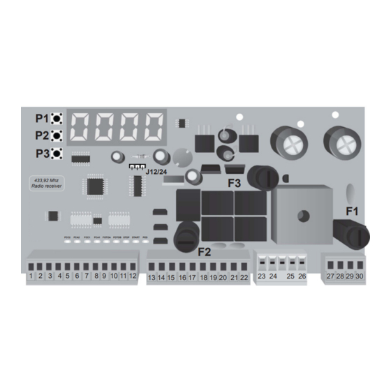
- Page 5 Scheme of the control unit and electrical connections + Antenna Common Services and Safeties Common Services and Safeties J12/24 433,92 Mhz Radio receiver Closing limit switch 2 Opening limit switch 2 Closing limit switch 1 FCC2 FCA2 FCC1 FCA1 FOTOA FOTOB STOP START Opening limit switch1 -7-...
- Page 6 Installation of the control unit Connection of the TENSION The control unit can be powered 12 Vac/24 Vac 12 Vac: Put the J12/24 as in the picture 230V input Primary Set to “0” the set up S 21. Transformer Low Tension input for transformer BATTERY 24 Vac:...
- Page 7 Connection of the COURTESY LIGHT To activate the courtesy light function, as shown in the picture S03 Set up Description In the terminal board 17 and 14 S 03 1 Courtesy light in the tension is available up to 255s LAMP output after.
- Page 8 3.10 Connection of the LIMIT SWITCHES In the picture is shown the connection of both limit switches but in this control unit you can use separately. So you can use only OPENING limit switches or only CLOSING limit switches. To deactivate the input LIMIT SWITCHES do as shown in the table Set up Value Description...
- Page 9 3.12 Connection of the PHOTO A (only closing) The normally closed contact of the receiver should be isolated from tension. If you you more couples of photo- beams the connection should be serial. POWER SUPPLY OF POWER SUPPLY OF THE PHOTO-BEAM THE PHOTO-BEAM If the input FOTO is not used,...
- Page 10 3.14 Connection of the PHOTO-B (in opening and closing) 15 16 The normally closed contact of the receiver should be isolated from tensions. If you you more couples of photo- beams the connection should be serial. POWER SUPPLY POWER SUPPLY OF THE RX OF THE TX If the input PHOTO-STOP...
- Page 11 3.16 Connection of the KEY LOCK - NEW LOCK SYSTEM Here you can see the connections of the key-lock. The function S 26 should be programmed to “0”: Set up Description S 26 Activate the KEY LOCK 1 - Deactivate the KEY LOCK (Default) KEY LOCK...
- Page 12 Function and adjustment Check the right function of the motors and the accessories as shown in the par. 4.2 and then, if you don’t know the working time of the motors, program the speed (see Par. 4.4), obstacle detection (see Par. 4.5) and activation/deactivation of the inputs.
- Page 13 Activation OF THE OUTPUTS The control unit can activate separately the electric-lock output, lamp, Photo-test, Light, Motors, Slow down: R ... Press P2 and P3 until you reach R... Keep pressed the button P1 to activate the output Release button P1 to deactivate the output R 02 R 06 R 10...
- Page 14 SPEED and SLOW DOWN OF THE MOTOR This operation can ad just fast the speed of Standard Set up Description Values the motor when opening and closing and the Value slow down. L 01 Standard speed from 1 to 10 MOT1 Make this operation before the memorization...
- Page 15 Managing of the remote control This receiver can manage standard codes from 12 till 64 bit and rolling codes HCS©. The first learned transmitter establish the code’s type that the receiver has to manage, it means that the transmitter has to have the same code’s type. The code can be from 12 to 64 bit and for rolling code HCS , the receiver will manage only the fix part of the code and not the rolling code counter.
- Page 16 Memorization of the remote controls This function can memorize one or more remote controls. It is sufficient that the receiver is compatible with the most bran- ded remote controls in the market, once you memorized the first remote control, the next codes should be of the same type. If it is a 12V remote control ( for example dip-switch) it will be memorized only 12 bits remote control.
- Page 17 WORKING TIME MEMORIZATION with START control To change the program of the control unit make as follow: T ... Press P2 and P3 until you will find T... Press P1 to choose the set up Press P2 and P3 to choose the value Press P1 to confirm the operation Set up Description Values confirmed...
- Page 18 TABLE INDICATING the FUNCTION of KEQS10 Set up of group “T” STANDARD DESCRIPTION VALUE NOTE VALUE T 01 Opening time MOT 1 from 2 to 127,5 s 15 s T 02 Closing time MOT 1 from 2 to 127,5 s...
- Page 19 Set up of group “S” STANDARD DESCRIPTION VALUE NOTE VALUE S 01 Logic of the control unit: from 1 to 6 1 - Fast reverse 2 - Collective use 3 - Single stable function 4 - Single stable with automatic re-closing after pause time 5 - Industrial use 6 - “Man Present”...
- Page 20 Set up of group “C” SET UP N° DESCRIPTION C 01 Memorization of the TX for START control C 02 Memorization of the TX for START control C 03 RESET of the MEMORY C 04 CANCELLATION of a SINGLE CODE Set up of group “R”...
- Page 21 NOTE:...
- Page 22 NOTE:...
- Page 23 Dichiarazione CE di conformità (secondo Direttiva 2006/42/CE, Allegato II, parte B) Il sottoscritto , Nome prodotto: KEQS10 Amministratore centrale elettronica di comando a bassa tensione DICHIARA CHE: IL PRODOTTO E’ CONFORME a quanto previsto dalla direttiva comunitaria: DIRETTIVA 2006/42/CE DEL PARLAMENTO EUROPEO E DEL CONSIGLIO del...
- Page 24 CASIT s.a.s. Stab.: Strada Pietra Alta 1 - 10040 CASELETTE (TO) Italy Tel. +39 011 9688230 Fax +39 011 9688363 Partita IVA 0050659.001.7 Reg. Trib. Torino N.654/62 C.C.I.A.A. 333122 - M: T0024777 www.casit-italy.com info@casit.it direzione@pec.casit.it...
Need help?
Do you have a question about the KEQS10 and is the answer not in the manual?
Questions and answers