Table of Contents
Advertisement
Quick Links
INSTALLATION MANUAL
Installation Manual
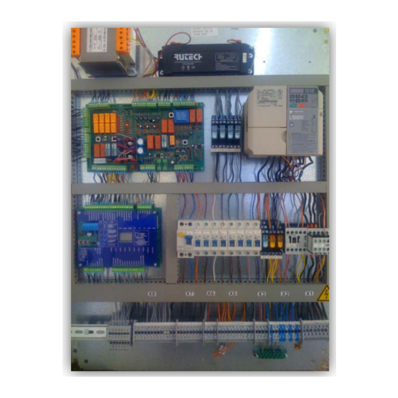
Lift Controller ISL_V2 Series
by IS technology
VERSION V2
(REV 2.4)
________________________________________________________________________
FACTORY - HEAD OFFICE:
PERREVOU 37, THESSALONIKI
54352, GREECE
TEL.: +30 231 220 9009
email: info@istechnology.gr
FAX.:+30 2310 943169
URL: www.istechnology.gr
________________________________________________________________________________________________
Copyright IS technology 2011
Advertisement
Table of Contents

Subscribe to Our Youtube Channel
Summary of Contents for IS Technologies ISL V2 Series
- Page 1 INSTALLATION MANUAL Installation Manual Lift Controller ISL_V2 Series by IS technology VERSION V2 (REV 2.4) ________________________________________________________________________ FACTORY - HEAD OFFICE: PERREVOU 37, THESSALONIKI 54352, GREECE TEL.: +30 231 220 9009 email: info@istechnology.gr FAX.:+30 2310 943169 URL: www.istechnology.gr ________________________________________________________________________________________________ Copyright IS technology 2011...
-
Page 2: Table Of Contents
INSTALLATION MANUAL INDEX 1. Technical Specification of Lift Controller ISL-V2. 1.1 Technical Features............Page 2. 1.2 Symbols ............... Page 3. 1.3 ISL_V2 Controller Terminal Description ....... Page 4. 1.4 Typical Wiring Diagram for ISL-V2 Controllers ..... Page 6. 1.5 Counting System Installation for ISL_V2 controllers ..Page 7. 2. -
Page 3: Technical Specification Of Lift Controller Isl-V2
INSTALLATION MANUAL 1. Technical Specification of Lift Controller ISL-V2. 1.1. Technical Features. • Control panel features Electrostatic Painted • Protection Class IP-54 • Wall mounting set included • Machine Room Stop Switch, Cabin at floor indication and power switch included 1.Traction Dimensions 800 x 700 x 180 mm... -
Page 4: Symbols
INSTALLATION MANUAL 1.2. Symbols. Terminal Group Voltage Description SYMBOL Description Χ1 400Vac 3 phase circuits (Supply, Motor Modules Output) Χ2 230Vac 1 phase (Supply, Lights) Fuse Χ3 <230Vac Doors, Cam, Brake control Encoder Χ4 48/12Vdc Valves Χ5 Terminal 110Vac or 48Vdc Safety elements Χ6 12Vdc... -
Page 5: Isl_V2 Controller Terminal Description
INSTALLATION MANUAL 1.3. ISL_V2 Controller Terminal Description. Category Terminal Name Description Group 3 phase connections (High Voltage 400Vac) Machine Room Ground Machine Room R,S,T Input of 3 phase supply – Mains L1, L2, L3. Machine Room U1,V1,W1 Output Motor (In traction 2 speed machine - Fast speed winding) Machine Room U2,V2,W2 Output Motor (In traction 2 speed machine - Slow speed winding) - Page 6 INSTALLATION MANUAL Χ7 Flat Cable +24, REV Inspection - (NC / +24Vdc) (Closed = Inspection / Opened = Normal) Χ7 Flat Cable +24, RUP Inspection Down - (NO / +24V). Χ7 Flat Cable +24, RDN Inspection Up - (NO / +24V). Χ7 ZA1 - ΖΑ2 Relevelling Zone Α...
-
Page 7: Typical Wiring Diagram For Isl-V2 Controllers
INSTALLATION MANUAL 1.4. Typical Wiring Diagram for ISL-V2 Controllers. -
Page 8: Counting System Installation For Isl_V2 Controllers
INSTALLATION MANUAL 1.5. Counting System Installation for ISL_V2 controllers. -
Page 9: Electronic Modules For Isl_V2 Controllers
INSTALLATION MANUAL 2. Electronic Modules for ISL_V2 Controllers. 2.1 Power Drive Module PDM_V3 (For Valve block drive). In ISL Lift Controllers and specific in Hydraulic lift Applications the valve block is driven by a specially designed module named PDM_V3. PDM module supports all known Valve blocks and ensures their fine operation with maximum safety. -
Page 10: Terminal Description
INSTALLATION MANUAL 2.3 Lift Control Board ISL_V2 (Astra_V2). 2.3.1 Terminal Description The Astra_V2 elevator control board is the "brain" of the controller. Controls all signals for lift applications up to 8 stops collective down. This board is designed according the EN81.1-2 norm and ensures that vertical transport is conducted with maximum safety. -
Page 11: Astra - V2 User Interface
INSTALLATION MANUAL 2.3.2 ASTRA - V2 User Interface. To operate or setup the ASTRA-V2 Elevator PCB module we can use the 4 ON Board Dip Switches and the 3 push button. The Astra - V2 Module has a 3 digit LCD screen where the user can see all necessary information for programming or troubleshoot the controller. -
Page 12: Fault Log
INSTALLATION MANUAL 2.3.3 Fault Log. Error Code Fault Description *Level Action taken Ι Safety circuit and/or door Waits for safety circuit to close opened during travel Ι Safety circuit opened during Waits for safety circuit to close, cancels travel calls if fault persists more than 5sec Ι... -
Page 13: Programming Menu
INSTALLATION MANUAL 2.3.4 Programming Menu. To Enter the programming Menu follow the steps: 1. Turn Off the controller 2. Put the Dip Switch No4 in ON position 3. Power on the controller 4. Navigate the Menu with Next and Prev Buttons and Press select for saving new values. To Leave programming Menu Just put the Dip Switch No4 back to Off position. - Page 14 INSTALLATION MANUAL IS technology PERREVOU 37 54 352, THESSALONIKI TEL: +30 2310 943169 24 Months FAX: +30 2310 943169 E-mail: info@istechnology.gr Product Guaranty Name: Address: Telephone: Fax: ISL Controller Type : Shipping Date Code Model The Product guaranty is valid within 24 months from shipping date and only if: ...
- Page 15 INSTALLATION MANUAL...
- Page 16 INSTALLATION MANUAL Declaration of Conformity CE EMC Compliance Standards and Directive: 89/336/EU & 95/54/EC The Company : IS technology PERREVOU 37 54 352, THESSALONIKI GREECE Declare that the products listed below are following the provisions of the 89/336/EU & 95/54/EC directive. The tests was made by EMC Hellas (Protocol No.: E10/033): Product: Type:...
Need help?
Do you have a question about the ISL V2 Series and is the answer not in the manual?
Questions and answers