Table of Contents
Advertisement
Quick Links
Advertisement
Table of Contents

Subscribe to Our Youtube Channel
Summary of Contents for C-Tech HYLN-5
- Page 1 ROLLER COMPACTOR HYLN-5...
-
Page 2: Table Of Contents
CONTENTS Preface ..................................1 Safety warning ................................1 Description ..............................3 Main technical parameters ..........................3 III. Main features and structure ..........................3 IV. Circuit and air circuit ............................6 Test procedure ............................. 10 VI. Software ............................... 12 VII. Installation and debugging .......................... 26 VIII. Maintenance, storage and transportation ....................30 Appendix 1 ................................ -
Page 3: Preface
Preface Thank you very much for choosing this instrument. This manual is specially used to guide users to use and maintain this instrument correctly. Please keep this manual carefully, and put it in an easy-to-find place for reference at any time. Before installing and using this instrument, you must read the manual carefully to ensure safe and correct use of this instrument. - Page 4 8. Please cut off the power supply when the instrument is not in use. When moving, maintaining, or disassembling the instrument, the power supply must be cut off to ensure the safety of personnel and the instrument. 9. Be careful when transporting the instrument. Sudden strong bumps or drops may cause damage to the instrument.
-
Page 5: Description
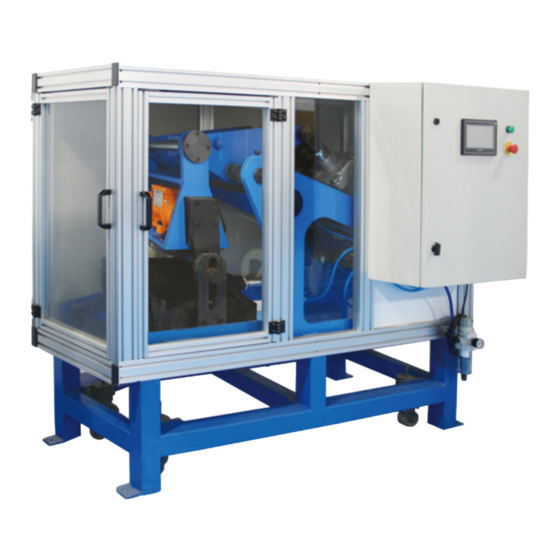
I. Description The HYLN-5 Roller compactor uses pneumatic loading and is suitable for making asphalt specimens using hot mix asphalt mixtures and simulating the on-site conditions. The specimens can be used for rutting test, sawn into beam shape for bending test, cut into column or cored for indirect tensile and residual strain test. - Page 6 4. The mold size of the roller compactor: 300×300mm, 300×400mm, 305×300mm, 305×400mm. Mold thickness: 40-120 mm, can be made according to user requirements, suitable for the use of the wheel tracking apparatus, and can automatically make specimen at one time according to the preset height or density.
- Page 7 LCD touch screen Power indicator Emergency stop Electrical cabinet control panel [LCD touch screen]: Control the action of the instrument through the screen. [Power indicator light]: When the instrument is powered on, the indicator light is on. [Power switch]: Control the on and off of the power supply of the instrument. It is recommended to turn off after cleaning the site.
-
Page 8: Circuit And Air Circuit
Roller compactor HYLN-5 IV. Circuit and air circuit Circuit Connect the power supply. The power supply required by the equipment is 220V AC. The yellow-green wire is the ground wire. - Page 9 The physical diagram of the circuit part The wiring schematic diagram of the circuit part is shown in the figure below. - 7 -...
- Page 10 - 8 -...
- Page 11 Air circuit The physical diagram of the air circuit part is shown in the figure below. Main valve Pressure sensor Physical diagram of the air circuit Electric proportional Speed control valve valve - 9 -...
-
Page 12: Test Procedure
V. Test procedure 1. Connect the air source first, then the power source. Turn on the [emergency stop switch] to power up the instrument (if there is no alarm sound, the instrument is operating normally). 2. The instrument automatically enters the [Startup] interface. Check whether the boxes in front of "parameter download completed"... - Page 13 ④. Click the "Pressure Correction Table" button to enter the [Pressure Correction Table] interface (as shown in Figure 6-9). Set seven groups of corresponding control voltage, feedback voltage and actual pressure, and click the "data download" button; WARNING! In order to use this instrument safely and correctly, please carefully read the precautions displayed on the [Startup] interface.
-
Page 14: Software
the instrument will start to run according to the parameters set in P1 Stage. After the P1 Stage is completed, the instrument will skip to the P2 Stage automatically, the word of “P2 Stage” will turn to red and the instrument will start to run according to the parameters set in P2 Stage. In this way, the instrument will automatically stop after the six test stage completed. - Page 15 Figure 6-1 Startup interface Please read the "Matters needing attention" carefully and strictly abide by it; View "Equipment Information". "Parameter download completed" and "correction table is downloaded" mark "√" in the box in front, indicating that the parameter download is normal; Click the "Enter the Test"...
- Page 16 [Set pressure (kN)]: Display the pressure value set in the current test stage, that is, the loading pressure set in the [Parameter Setting] interface; Figure 6-2 test interface [Current roundtrip times]: Display the number of round trips to the current test stage; [Set roundtrip times]: Display the total number of round trips set in the current test stage, that is, the number of round trips set in the [Parameter Setting] interface;...
- Page 17 NOTE 1. The font color of the button is red, indicating that this stage is currently ongoing. 2. The vibration motor does not start during the preloading. This stage is only the preparation stage before the start of the test. The purpose is to make the fan-shaped steel roller and the test mold cooperate in advance to avoid loud noise due to the loading pressure at the beginning of the test.
- Page 18 [Intermediate position signal]: indicates the intermediate position signal of the round-trip cylinder. The green indicates that the cylinder is not in the intermediate position, and the red indicates that the cylinder is in the intermediate position. [Current pressure (kN)]: Display the real-time loading pressure; [Loading position]: Click this button to move the round-trip cylinder, and stop when it reaches the loading position, which is convenient for loading and unloading of test molds;...
- Page 19 [Data Save & Recovery]: Click this button to enter the [Data Save & Recovery] interface, as shown in Figure 6-10; [Help notes]: Click this button to jump to the interface of [Help notes], as shown in Figure 6-11; [Return]: Click this button to return to the [Test] interface. Figure 6-4 Help &...
- Page 20 Figure 6-5 IO testing interface [JQ1], [JQ2], [JQ3], [JQ4], [JQ5], [JQ6], [JQ7], [JQ8]: Click the button, the font of the button will turn red, and the corresponding light on the circuit board will light up. The corresponding lights of JQ1~JQ8 are M01~M08 on the circuit board, and their positions are shown in Figure 6-6.
- Page 21 Figure 6-6 M01~M08 on the circuit board Signal testing interface In the [Help & Settings] interface shown in Figure 6-4, click the "Signal Testing" button, and the instrument will enter the [Signal Testing] interface, as shown in Figure 6-7. NOTE This interface is mainly used for engineers to repair and test, and does not need to be mastered by the customer.
- Page 22 cylinder; [Vibration frequency]: Display the current frequency of the vibration motor when it is working; Figure 6-7 Signal testing interface [Round-trip cylinder alignment signal] [Round-trip cylinder top signal] [Round-trip cylinder signal]: Same as the IO test interface, see Figure 6-5; [Single vibration frequency]: Set the single vibration frequency for vibration motor debugging;...
- Page 23 touch screen; click the button again, the pressurized cylinder returns to the starting position and stops. [Round-trip cylinder]: This button is used to debug the round-trip cylinder. Click this button, the font of the button changes to red, and the round-trip cylinder keeps moving back and forth, and the number of round trips is displayed in the [Current Round-trip times];...
- Page 24 [Data Download]: Click this button to transfer the set parameters to the control card. After changing the parameters, you must perform this operation to make the parameters take effect. [Data upload]: Display the parameters of the control card in the interface, and you can verify whether the parameters are the values you want to set.
- Page 25 is the output voltage of the electric proportional valve. The actual pressure (kN) is the pressure sensor indication (kg) × 9.8. Measuring method of pressure correction table: ①. In the [Pressure Correction Table] interface, click the "intermediate position" button to adjust the round-trip cylinder to the middle of the cylinder stroke, so that the fan-shaped steel roller and the mold are as vertical as possible.
- Page 26 [Data upload]: Display the parameters of the control card in the interface, and you can verify whether the parameters are the values you want to set. [Help]: Click this button to jump to the [Help-Pressure Correction Table] interface to view the pressure correction method;...
- Page 27 Figure 6-10 Data save & recovery interface Help notes interface In the [Help & Settings] interface shown in Figure 6-4, click the "Help notes" button to enter the [Help notes] interface, as shown in Figure 6-11. Figure 6-11 Help notes interface - 25 -...
-
Page 28: Installation And Debugging
[1: Test step]: Click this button to jump to the [Test step] interface to view the test operation steps; [2: Feeding step]: Click this button to jump to the [Feeding step] interface to view the test loading operation steps; [3: Unloading step]: Click this button to jump to the [Unloading step] interface to view the test unloading operation steps;... - Page 29 NOTE The air source needs to be equipped by the user. Air volume: not less than 0.9m /min, pressure 1.0mpa. Inverter debugging Here only lists the parameters used in the communication debugging of the inverter. In case of other faults or problems with the inverter, please refer to the inverter manual or ask a professional. The inverter panel is shown in Figure 7-1.
- Page 30 Function parameters to be set: When the parameters are P135~P139, the power is turned from OFF to ON, the changed parameter value is valid. ①. P003. Run command selection: set the setting value to 7, that is, the communication command state, to make the running command sent by communication valid;...
- Page 31 graduated scale knurled nut pointer Safety regulations 1. The operator must pass technical training, understand and master the operation, adjustment, technical maintenance and technical safety of the machine before using the instrument. 2. Pay attention to the technical parameters of the machine, especially the environmental conditions must meet the requirements.
-
Page 32: Maintenance, Storage And Transportation
6. All adjustments and maintenance can only be carried out after stopping work and turning off the main power supply; repair and maintenance are prohibited when the machine is runing; the power supply must be cut off when troubleshooting the instrument. WARNING! 1. - Page 33 a. Clean the machine. You can wipe the outer surface of the machine with a dry soft cloth. Especially need to pay attention to whether there are sundries on the wheels of the trolley and guide rails. If so, you need to clean the debris and apply lubricating oil on the surface. In places where there is too much dust and cannot be wiped, compressed air can be used to blow.
- Page 34 ②. Fill all bearings and lubrication parts with enough lubricating oil. ③. Cut off the main power and gas source. ④. Put the dust cover on the machine. During storage, the instrument is not allowed to be exposed to sunlight or rain, and is not allowed to be placed upside down or stacked.
- Page 35 Appendix 1 If the emergency stop is pressed or the protective door is opened during automatic operation, the instrument will pause and cut off the main gas source to protect personal safety. After troubleshooting, press the "Clear Alarm" button, and the instrument will continue to work. Common faults and troubleshooting methods Fault Reason...
- Page 36 Appendix 2 Status code description Device status code Description The instrument is normal The voltage of the pressure sensor (that is, the feedback voltage) is abnormal after the pressurized cylinder is pressed down Round-trip cylinder does not go back and forth for 10 seconds The air pressure is abnormal Security door 1 is not completely closed Security door 2 is not completely closed...
- Page 37 - 35 -...
Need help?
Do you have a question about the HYLN-5 and is the answer not in the manual?
Questions and answers