Table of Contents
Advertisement
Quick Links
Advertisement
Table of Contents

Subscribe to Our Youtube Channel
Summary of Contents for AITECS 2015
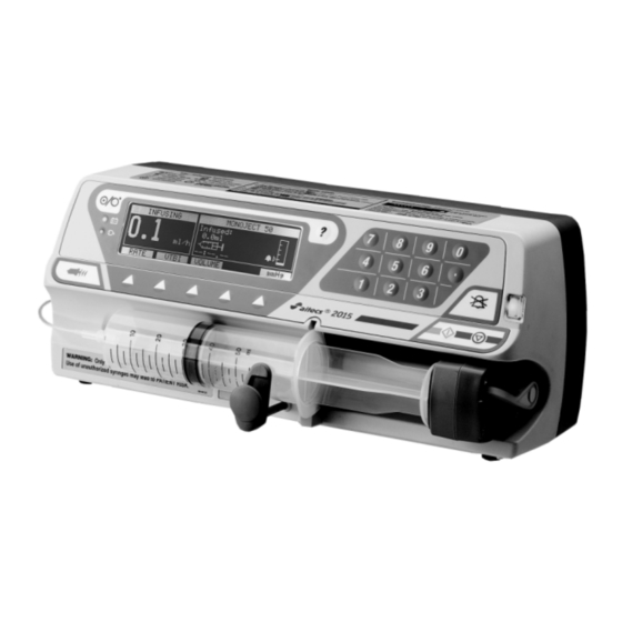
- Page 1 Service Manual AITECS 2015 ® S Y R I N G E I N F U S I O N P U M P BS036027EN-P06 Prior to servicing this pump, read this manual and the pump’s Operator’s Manual carefully to fully understand the pump’s...
-
Page 2: Table Of Contents
BATTERY MONITORING UNIT COMPONENT LOCATION DIAGRAM......54 MECHANICAL ASSEMBLY DRAWINGS AND PART LIST............. 55 9.1. PART LIST..........................55 9.2. FRONT CASE ASSEMBLY ....................57 9.3. REAR CASE ASSEMBLY ...................... 69 9.4. FINAL ASSEMBLY ........................ 73 SPARE PARTS LISTING ......................75 Aitecs 2015 Service Manual... - Page 3 10.1. SPARE ACCESSORIES ......................75 10.2. SPARE LABELS / PUBLICATIONS ..................75 10.3. SPARE ELECTRICAL COMPONENTS................. 76 10.4. SPARE MECHANICAL COMPONENTS ................76 ANNEX A ROUTINE MAINTENANCE & CHECKOUT PROCEDURE ........78 Aitecs 2015 Service Manual...
-
Page 4: Introduction
1.1. GENERAL INFORMATION The Aitecs 2015 syringe pump is designed to accurately control the delivery of solution to the patient by means of a disposable syringe. The Aitecs 2015 syringe pump is compatible with a wide range of standard, single-use, disposable Luer-lock syringes, ranging from 10ml to 100ml in size. -
Page 5: Service Contacts
1.3. SERVICE CONTACTS VILTECHMEDA, 125 Kalvariju Str., 08221 Vilnius, Lithuania. E-mail: service@aitecs.com Aitecs 2015 Service Manual... -
Page 6: Technical Description
Motor speed and direction is monitored by means of the encoder. It is composed of two photo- interrupters D1, D2 and a 9 slot-encoding disk mounted on the stepper motor shaft. Quadrature signals (Tax1, Tax2) are transferred to the Drive Unit board via P6 connector. Aitecs 2015 Service Manual... - Page 7 The edge of the ruler is punched with the slots distributed with various intervals in certain pattern. Each slot passing the gap generates electrical pulse when the photo interrupter is moved along the ruler. Microcontroller permanently monitors width of intervals in Aitecs 2015 Service Manual...
-
Page 8: Electronic Board
Software instructions are stored in 1-Megabyte FLASH memory U10. Device constant parameters are stored in 8-kilobyte SPI EEPROM, U14. Temporary variables are stored in 128 - kilobyte SRAM U8 with real time clock and lithium battery. Aitecs 2015 Service Manual... - Page 9 +5 V to it. For this sake pin 4 of JP10 is also connected with the P7.7 output of microcontroller (pin 26) and output of watchdog via the D21 and D22 correspondingly; logic ‘1’ at any of these two Aitecs 2015 Service Manual...
- Page 10 U6A, which acts as follows: 1) Stops motor (via the D22), 2) Activates red alarm LED D1 (via the D4), 3) Activates the nurse call circuit located in the Supply Unit (via the D16), Aitecs 2015 Service Manual...
-
Page 11: Drive Unit Board
Quadrature signals from the motor encoder are processed by means of the decoder built on the U6, U7, and U8 integrated circuits. 9 square pulses are generated at the TAX output (pin2 of JP2) during one revolution of motor shaft. The “BACKWARDS” output is used to indicate Aitecs 2015 Service Manual... -
Page 12: Power Supply Unit
12 VDC source. 2.5. IRDA/RS232/NURSE CALL INTERFACE 2.5.1. IRDA interface Serial infrared data communication is operating in accordance with the IRDA standard using modulator-demodulator U4 and transceiver U5 located on the power supply’s PCB. Aitecs 2015 Service Manual... -
Page 13: Bootstrap Loader Unit
JP6 connector of the Electronic board. It allows launching the U12 microcontroller by means of manual reset signal, maintains Power Supply Unit active, commutates UART via the RS232 interface and configures the microcontroller so as to launch its internal bootstrap loader. Aitecs 2015 Service Manual... -
Page 14: User Configuration Menu
To perform a programming operation, the following is required: - Aitecs 2015 Firmware Upload Utility must be installed and configured on the computer that is being used. - Either RS232 extension cable must be connected between the COM port of the computer and the 9-way ‘D’... -
Page 15: Calibration
4.2.2. Loading Bootstrap In order to perform a programming operation, the following should be in place: - Aitecs 2015 Firmware Upload Utility should be installed and configured on the computer that is being used. - Having opened the pump housing, Bootstrap Loader Unit should be connected to the Electronic board connector JP6 (Bootstrap Loader Unit switch should be in ON position). - Page 16 RUN softkey and keep it depressed, allowing the transmission to run until the pressure meter reads (148±1.5) cmHg. When approaching the target value, it is recommended to run transmission in short steps, since if you fail to stop transmission timely and target value is Aitecs 2015 Service Manual...
- Page 17 (mAh). While the calibration cycle is active the battery related information is displayed on the pump screen. At the end of the cycle the screen should show CALIBRATION COMPLETED. Press the QUIT softkey to exit. Aitecs 2015 Service Manual...
-
Page 18: Testing
This test enables checking of the motor operation. During test no syringe should be installed. Select Motor from the testing menu and press the OK softkey. Having finished testing press the QUIT softkey to return to TESTING menu. Aitecs 2015 Service Manual... - Page 19 This test enables checking of the watch-dog circuit operation. Select Watch-Dog from testing menu and press the OK softkey. Initially the watch-dog circuit is applied with an over frequency signal and later with an under frequency signal. When test completed switch off the pump using the OFF key. Aitecs 2015 Service Manual...
-
Page 20: Recommended Routine Maintenance And Testing
Check the operation of the pole clamp screw. Check it is not loose and that the threads are not damaged. Check that it folds away correctly. Inspect the AC power supply inlet and cable for sings of damage. Aitecs 2015 Service Manual... -
Page 21: Battery Test
When pump will stop and indicate OCCLUSION read the maximum pressure recorded by pressure meter. Readings shall be within (63 - 107) cmHg range. If recorded value is outside this range, re-calibrate the force sensor in accordance with 4.3.3 and repeat this test. Aitecs 2015 Service Manual... -
Page 22: Trouble-Shooting
If fluid ingress is suspected the pump should be inspected internally. Clean and dry out the pump. Take care to ensure dried deposits do not remain on the PCBs or other electrical components. Replace any damaged PCBs or components. Aitecs 2015 Service Manual... -
Page 23: Trouble-Shooting By Fault Symptom
Operator’s Manual. Check backlight circuit If necessary replace interconnection on Electronic Electronic board. board Check Display Unit and its If necessary replace Display connection with the Unit. Electronic board connector JP13. Aitecs 2015 Service Manual... - Page 24 Check encoder unit. If necessary replace encoder when it should. unit. Check stepper motor. If necessary replace stepper motor. Check Drive Unit board. If necessary replace Drive Unit board. Check motor belt. If necessary replace motor belt. Aitecs 2015 Service Manual...
- Page 25 Unit. Electronic board connector JP3. Check IRDA circuit If necessary replace interconnection on Electronic Electronic board. board. Versatile clamp does not fix Check versatile clamp. If necessary replace versatile to the pump. clamp. Aitecs 2015 Service Manual...
-
Page 26: Trouble-Shooting By Failure Codes
Keypad monitor software module has failed. Power off then on. If failure code recurs, replace software. WD01 W-D circuit failed Replace Electronic board WD02 W-D circuit failed Replace Electronic board WD03 W-D circuit failed Replace Electronic board or Drive Aitecs 2015 Service Manual... - Page 27 Check Drive Unit board and replace it if necessary. Check Stepper Motor and replace it if necessary. Check Motor Belt and replace it if necessary. BAR01 Barrel sensor is damaged. Check barrel sensor and replace it if necessary. Aitecs 2015 Service Manual...
- Page 28 Replace syringe pusher or drive if necessary. SF01 Syringe force sensor reading out of range. Calibrate syringe force sensor. If the problem persists: Check syringe force sensor and replace syringe pusher with syringe Aitecs 2015 Service Manual...
- Page 29 Power off then on. If failure code recurs, replace software. LED01 LEDs control software module has failed. Power off then on. If failure code recurs, replace software. AL01 Alarm manager software module has failed. Power off then on. If failure code Aitecs 2015 Service Manual...
- Page 30 Power off then on. Set default EEPROM. parameters. If failure code recurs, replace Electronic board if necessary. IF01 Pump software not compatible with Replace software hardware revision OTH01 Other failures Check log, if necessary replace software Aitecs 2015 Service Manual...
-
Page 31: Repair
Use a knife to find the edge of the syringe barrel sensor cover (28) and carefully peel it back. 7.2.1.2 Keypads removal Detach the flexi-cables of the keypad K1(25), K2(26) from the Electronic board (23). Carefully access the edge of the keypad, peel it back. Aitecs 2015 Service Manual... - Page 32 (16). 7.2.1.9 Syringe pusher removal Disconnect flexi-cables. Remove syringe pusher (12) from the stops (13) by pushing it to the left. Remove stops (13) from the tube using a screwdriver. Remove syringe pusher (12). Aitecs 2015 Service Manual...
- Page 33 Disconnect the encoder unit (3) cable from Drive Unit board (17). Remove the screw (69), the nut (70) and remove encoder unit (3). 7.2.1.17 Syringe barrel sensor removal Remove the Electronic board. Remove the drive. Remove the screw (61) and remove syringe barrel sensor (1). Aitecs 2015 Service Manual...
- Page 34 B6660032 (8) cable to Drive Unit board (17). 7.2.2.5 Encoder ruler installation Fit the encoder ruler (7) and secure with the screw (67) and the nut (58) via washer (72). Perform pusher position sensor calibration procedure in accordance with the 4.3.2. Aitecs 2015 Service Manual...
- Page 35 Syringe size sensor installation Carefully insert the syringe size sensor (19). Secure with 2 screws (62). Connect the syringe size sensor (19) cable to the Electronic board (23). Perform syringe size sensor calibration procedure in accordance with the 4.3.1. Aitecs 2015 Service Manual...
- Page 36 Syringe barrel sensor cover installation Using isopropyl alcohol clean the case surface ensuring all old adhesive residue is removed where the syringe barrel sensor cover (28) will be positioned. Glue the syringe barrel sensor cover (28) using instant glue. Aitecs 2015 Service Manual...
-
Page 37: Rear Case And Sub-Assemblies
Remove the RS232 connector unit screws (51) and carefully withdraw the RS232 connector unit (34). 7.3.1.5 Piezotransducer unit removal The piezotransducer (30) is glued to the rear case. Using the small knife carefully remove the piezotransducer (30) from the rear case. Aitecs 2015 Service Manual... -
Page 38: Torque Guide
These values are for the first insertion of screws and fasteners. When selecting a torque for servicing activity, be aware that refastening will require slightly less torque than the initial manufacture. Over-tightening of screws and fasteners can cause damage. The manufacturer cannot be held responsible for such damage caused. Aitecs 2015 Service Manual... - Page 39 Secure RS232 connector Nut S4,5 (FCN770-A07) L5555023 50cNm unit Secure switching power Screw ISO 7046 M3x16 B1000125 50cNm supply Nut ISO 4032 M3 B1001030 50cNm Secure power supply unit Nut ISO 4032 M6 B1001060 grounding wire Aitecs 2015 Service Manual...
- Page 40 Final Assembly: Stage Description Component Description Part No Established Process Torque Secure battery Screw ISO 7049 ST2,9x9,5-F-Z B1000219 40cNm compartment lid Secure Front Case to Rear Screw ISO7045 M4x10 B1000062 case Aitecs 2015 Service Manual...
-
Page 41: Electrical Schematic Diagrams, Component Location Diagrams
8. ELECTRICAL SCHEMATIC DIAGRAMS, COMPONENT LOCATION DIAGRAMS 8.1. ELECTRICAL BLOCK DIAGRAM OF THE PUMP Aitecs 2015 Service Manual... -
Page 42: Electrical Schematic Diagram Of The Pump
8.2. ELECTRICAL SCHEMATIC DIAGRAM OF THE PUMP Aitecs 2015 Service Manual... - Page 43 ELECTRICAL SCHEMATIC DIAGRAM OF THE PUMP (CONTINUED) Aitecs 2015 Service Manual...
- Page 44 ELECTRICAL SCHEMATIC DIAGRAM OF THE PUMP (CONTINUED) Aitecs 2015 Service Manual...
-
Page 45: Electronic Board Schematic Diagram
8.3. ELECTRONIC BOARD SCHEMATIC DIAGRAM Aitecs 2015 Service Manual... - Page 46 ELECTRONIC BOARD SCHEMATIC DIAGRAM (CONTINUED) Aitecs 2015 Service Manual...
- Page 47 ELECTRONIC BOARD SCHEMATIC DIAGRAM (CONTINUED) Aitecs 2015 Service Manual...
- Page 48 ELECTRONIC BOARD SCHEMATIC DIAGRAM (CONTINUED) Aitecs 2015 Service Manual...
-
Page 49: Electronic Board Component Location Diagram
8.4. ELECTRONIC BOARD COMPONENT LOCATION DIAGRAM Aitecs 2015 Service Manual... -
Page 50: Drive Unit Board Schematic Diagram
8.5. DRIVE UNIT BOARD SCHEMATIC DIAGRAM Aitecs 2015 Service Manual... -
Page 51: Drive Unit Board Component Location Diagram
8.6. DRIVE UNIT BOARD COMPONENT LOCATION DIAGRAM Aitecs 2015 Service Manual... -
Page 52: Power Supply Unit Schematic Diagram
8.7. POWER SUPPLY UNIT SCHEMATIC DIAGRAM Aitecs 2015 Service Manual... -
Page 53: Power Supply Unit Component Location Diagram
8.8. POWER SUPPLY UNIT COMPONENT LOCATION DIAGRAM Aitecs 2015 Service Manual... -
Page 54: Battery Monitoring Unit Component Location Diagram
8.9. BATTERY MONITORING UNIT COMPONENT LOCATION DIAGRAM Aitecs 2015 Service Manual... -
Page 55: Mechanical Assembly Drawings And Part List
Silicon gasket B1000051 Screw ISO 1207 M3x12 B1001060 Nut ISO 4032 M6 L5555023 Screw kit (FCN770-A07) L5555022 Retaining clips with screw kit (1KT0006) B1000125 Screw ISO7046 M3x16 B1000059 Screw ISO 1580 M3x25 B1000057 Screw ISO 1580 M3x20 Aitecs 2015 Service Manual... - Page 56 Label (WARNING) B8180227 Label (WARNING, syringes 5-100ml) B8180138 Label (Aitecs LOGO) B8917013-05 Silicon gasket B8180127 Label (RS232) B8180140 Label (Do not disassemble) B8180139 Label (instruction) B8180152 Label (clip) B8180205 Label (alignment) B8180082 Label (electrostatic) V8180085 Label (ground) Aitecs 2015 Service Manual...
-
Page 57: Front Case Assembly
9.2. FRONT CASE ASSEMBLY 9.2.1 Syringe barrel sensor 9.2.2 Encoder Unit Aitecs 2015 Service Manual... - Page 58 9.2.3 Motor Unit 9.2.4 Motor belt Aitecs 2015 Service Manual...
- Page 59 Motor belt (continuation) 9.2.5 Sensor unit B6660032 Aitecs 2015 Service Manual...
- Page 60 9.2.6 Encoder ruler 9.2.7 Drive Aitecs 2015 Service Manual...
- Page 61 Drive (continuation) 9.2.8 Syringe support Aitecs 2015 Service Manual...
- Page 62 9.2.9 Syringe pusher Syringe pusher (continuation) Aitecs 2015 Service Manual...
- Page 63 9.2.10 Syringe pusher drive 9.2.11 Drive Unit board Aitecs 2015 Service Manual...
- Page 64 Drive Unit board (continuation) 9.2.12 Syringe size sensor Aitecs 2015 Service Manual...
- Page 65 9.2.13 Syringe clamp 9.2.14 Display Unit Aitecs 2015 Service Manual...
- Page 66 9.2.15. Electronic board 9.2.16. 9.2.15 9.2.16 9.2.17 9.2.18 Electronic board (continuation) Aitecs 2015 Service Manual...
- Page 67 9.2.16. SRAM 9.2.17. Keypads Aitecs 2015 Service Manual...
- Page 68 9.2.18. Syringe barrel sensor cover Aitecs 2015 Service Manual...
-
Page 69: Rear Case Assembly
9.3. REAR CASE ASSEMBLY 9.3.1 RS232 connector unit and piezotransducer unit 9.3.2 Mains filter unit and 12VDC&Nurse call unit Aitecs 2015 Service Manual... - Page 70 9.3.3 Switching power supply 9.3.4 Power supply unit Power supply unit (continued) Aitecs 2015 Service Manual...
- Page 71 Power supply unit (continued) 9.3.5 Battery unit Aitecs 2015 Service Manual...
- Page 72 Battery unit (continuation) Aitecs 2015 Service Manual...
-
Page 73: Final Assembly
9.4. FINAL ASSEMBLY Final assembly (continuation) Aitecs 2015 Service Manual... - Page 74 Final assembly (continuation) Final assembly (continuation) Aitecs 2015 Service Manual...
-
Page 75: Spare Parts Listing
Aitecs 2015 Firmware Upload Utility B6690007 Bootstrap Loading Unit 10.2. SPARE LABELS / PUBLICATIONS PART NUMBER DESCRIPTION BS036027EN Service Manual Aitecs 2015 Syringe Infusion Pump BN036018XX Operator’s Manual Aitecs 2015 Syringe Infusion Pump B8180137XX-P04 Label (serial number) B8180125XX-P01 Label (WARNING) -
Page 76: Spare Electrical Components
10.4. SPARE MECHANICAL COMPONENTS PART NUMBER DESCRIPTION B6678004 Syringe pusher B6337019 Syringe pusher drive B6210004 Syringe size sensor V8413101 Motor timing belt B8703025 Syringe barrel sensor cover B8127005 Syringe clamp B8126086 Syringe support B6400001 Versatile clamp B6290003 Encoder ruler Aitecs 2015 Service Manual... - Page 77 B6337021 Drive V5511152 Cap RS232 V5511153 Cap 12VDC&Nurse call L5555024 Clip B8280007 Shaft V6300400 Aitecs 2015 Service Manual...
-
Page 78: Annex Aroutine Maintenance & Checkout Procedure
Check occlusion pressure level (L5: 63cmHg-107 cmHg) RESULT: ________cmHg Check software version. Version Number: ________________ Perform drive sensors test Perform syringe size sensor test Perform pusher position sensor test Perform motor test Perform display test Perform nurse call test Aitecs 2015 Service Manual... - Page 79 Perform watch-dog test Perform electrical safety test (class I, type CF) Comments: _____________________________________________________________________________ _____________________________________________________________________________ _____________________________________________________________________________ _____________________________________________________________________________ Tested by: _________________________________ _________________________ First Name Last Name Signature Date: _______________________ Reviewed by: _______________________________ _________________________ First Name Last Name Signature Date: _____________________ Aitecs 2015 Service Manual...
Need help?
Do you have a question about the 2015 and is the answer not in the manual?
Questions and answers