Table of Contents
Advertisement
Quick Links
ICC
INDUSTRIAL CONTROL COMMUNICATIONS, INC.
Multiprotocol Ethernet Interface
Thank you for purchasing the OPC-PRT3 Multiprotocol Ethernet Interface.
•
This product is designed to connect the FRENIC-MEGA, FRENIC-HVAC, FRENIC-HVAC-P,
FRENIC-AQUA, and FRENIC-Ace series of inverters to Ethernet communication networks.
Please read this instruction manual thoroughly in order to become familiar with the proper
interface handling, installation and usage procedures.
•
Improper handling may inhibit correct operation or cause premature interface failure.
•
Please deliver this instruction manual to the end user of the interface, and retain it in an
accessible location.
•
For inverter usage instructions, please refer to the applicable inverter instruction manual.
January 26, 2022
Part #11162
OPC-PRT3
Instruction Manual
© 2022 ICC
Advertisement
Table of Contents

Related Manuals for ICC OPC-PRT3

Summary of Contents for ICC OPC-PRT3
- Page 1 Instruction Manual INDUSTRIAL CONTROL COMMUNICATIONS, INC. OPC-PRT3 Multiprotocol Ethernet Interface Thank you for purchasing the OPC-PRT3 Multiprotocol Ethernet Interface. • This product is designed to connect the FRENIC-MEGA, FRENIC-HVAC, FRENIC-HVAC-P, FRENIC-AQUA, and FRENIC-Ace series of inverters to Ethernet communication networks.
- Page 2 OPC-PRT3 Multiprotocol Ethernet Interface Instruction Manual Part Number 11162 Printed in U.S.A. ©2022 Industrial Control Communications, Inc. All rights reserved Industrial Control Communications, Inc. reserves the right to make changes and improvements to its products without providing notice. Notice to Users PRODUCTS ARE NOT AUTHORIZED FOR USE AS CRITICAL COMPONENTS IN LIFE-SUPPORT DEVICES OR SYSTEMS.
- Page 3 These safety precautions are of utmost importance and must be observed at all times. Security information ICC provides products and solutions that support the operation of plants, systems, machines and networks. In order to protect these critical assets against cyber threats, it is necessary to implement and continuously maintain a holistic, state-of-the-art industrial security concept.
- Page 4 Installation and Wiring • To avoid electrical shock, remove all power from the inverter and wait at least five minutes prior to starting installation. Additionally, confirm that the DC link bus voltage as measured between the P (+) and N (-) terminals is less than 25 VDC. •...
- Page 5 Maintenance, inspection, and parts replacement • To avoid electrical shock, remove all power from the inverter and wait at least five minutes prior to starting inspection. Additionally, confirm that the DC link bus voltage as measured between the P (+) and N (-) terminals is less than 25 VDC. •...
-
Page 6: Table Of Contents
− TABLE OF CONTENTS − PRE-OPERATION INSTRUCTIONS ............. 8 Product Overview ....................8 Features and Specifications .................. 8 Unpacking and Product Confirmation ..............13 1.3.1 Shipment Confirmation ..................... 13 1.3.2 Component Overview....................... 14 LED Indicators ....................... 15 1.4.1 Network Status LED ......................15 1.4.2 Module Status LED ...................... - Page 7 Monitor Device Parameters .................. 40 6.10 Backup and Restore Parameters ................. 41 6.11 Restore Factory Settings ..................42 6.12 Help......................... 42 EMBEDDED WEB SERVER ............... 43 Overview ........................ 43 Customizing the Embedded Web Server ............43 7.2.1 Customization Overview ....................43 7.2.2 XTPro Overview .......................
- Page 8 10.2.14 ControlLogix Example: Reading and Writing MSG Instructions ........76 10.3 Allen Bradley CSP (PCCC) ................... 77 10.3.1 Overview .......................... 77 10.3.2 Explicit Messaging Via Read/Write Services ..............77 10.3.3 Inverter Function Code File Number Offset Format ............77 10.3.4 SLC-5/05 Example: Read Function Codes ............... 79 10.3.5 SLC-5/05 Example: Reading and Writing .................
-
Page 9: Pre-Operation Instructions
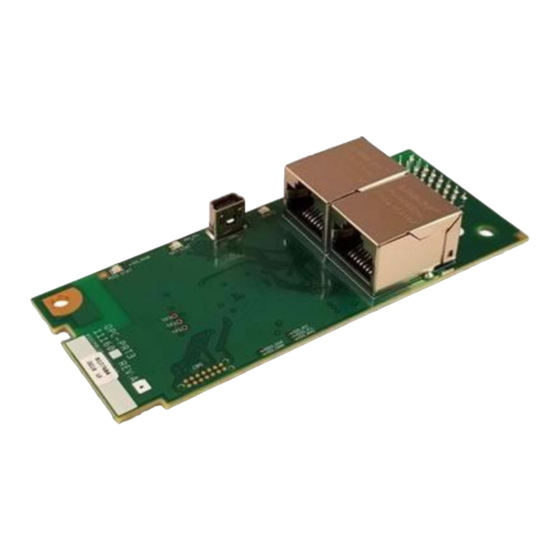
1 PRE-OPERATION INSTRUCTIONS Product Overview The OPC-PRT3 Multiprotocol Ethernet interface allows information to be transferred seamlessly between a FRENIC-MEGA, FRENIC-HVAC, FRENIC-HVAC-P, FRENIC-AQUA, or FRENIC-Ace inverter and several Ethernet-based fieldbus networks with minimal configuration requirements. The interface installs directly onto the inverter, and presents two RJ-45 jacks with an embedded 10BASE-T/100BASE- TX Ethernet switch for connection to the Ethernet network. - Page 10 Table 2: General Hardware Specifications Item Description Power Supply Directly powered by the inverter Referenced to inverter’s 5V power supply ground Grounding LED Indicators Module Status, Network Status, 2 x Ethernet Link/Activity USB Port USB 2.0, mini-B 5-pin Table 3: Ethernet Hardware Specifications Item Description Number of Ports...
- Page 11 Table 5: EtherNet/IP Specifications Item Description Conformance Tested ODVA EtherNet/IP Declaration of Conformity (CT-13) Product Type Code 2 (AC Drive) AC/DC Drive Profile UCMM Class 3 (Explicit) Messaging Class 1 (Implicit I/O) Messaging Class 1 Unicast T→O Class 1 Multicast T→O Number of Connections 16 (Total for both Class 1 and Class 3) Min 1ms...
- Page 12 Table 6: Allen Bradley CSP (PCCC) Specifications Item Description PLC5 Read (DF1 protocol typed read, 0x68) , PLC5 Word Range Read (DF1 protocol word range read, 0x01), Read Services SLC Read (DF1 protocol protected typed logical read with three address fields, 0xA2) PLC5 Write (DF1 protocol typed write, 0x67) , PLC5 Word Range Read (DF1 protocol word range write, 0x00), Write Services...
- Page 13 Table 8: PROFINET Specifications Item Description Conformance Tested PNIO Tester V3.2.1 (4432), PROFINET V2.31 Protocol Level RT (real-time) RT Conformance Class Class B Netload Class I/O Cycle Time Min 1ms I/O Input Size Max 32 input words, user configurable I/O Output Size Max 32 output words, user configurable Media Redundancy Protocol Client Discovery, set station name, set IP address...
-
Page 14: Unpacking And Product Confirmation
Some drives may require an additional option attachment or enclosure: Contact Fuji. • OPC-PRT3 interface board (refer to Figure 1). • Two M3 x 6mm mounting screws (see Figure 2). Figure 2: M3 x 6mm Mounting Screw... -
Page 15: Component Overview
Module Status LED Standoff mounting hole Positioning notch Figure 3: OPC-PRT3 Component Overview Positioning Notch Aligns with the positioning key on the inverter chassis to ensure that the interface card is installed into the correct communication port (refer to section 2.2). -
Page 16: Led Indicators
LED Indicators 1.4.1 Network Status LED LED Activity Status Note Device Off The inverter power is off Green Blink / Startup Startup blink sequence Red Blink Green Blink No Connection EtherNet/IP connection is not established Green Off No Connection PROFINET connection is not established Connection Green On EtherNet/IP or PROFINET connection is established... -
Page 17: Installation
• Only one additional option card may be used when the OPC-PRT3 is installed in the inverter. If two additional option cards are required, please consult with the factory first to confirm compatibility. - Page 18 Rest the left-hand side of the interface card on the control PCB’s A-port mounting support. Align the positioning notch on the interface card with the A-port positioning key, and then slide the interface card to the left to engage the key into the notch. Refer to step in Figure 5.
-
Page 19: Installation Procedure For Frenic-Ace Inverter
Installation Procedure for FRENIC-Ace Inverter Before installing the interface card, perform all wiring for the main circuit terminals and control circuit terminals. Some drives may require an additional option attachment or enclosure: Contact Fuji. Remove the front cover from the inverter to expose the control printed circuit board (control PCB). Install the interface card according to the inverter capacity as shown in Figure 7, Figure 8, or Figure 9. - Page 20 Interface Card Connector Board Option Case Figure 7: Installation for 15 kW and Smaller Inverters...
- Page 21 Interface Card Connector Board Option Case Figure 8: Installation for 18.5 kW to 22 kW Inverters...
- Page 22 Interface Card Connector Board Option Case Figure 9: Installation for 30 kW and Larger Inverters Engage connector CN1 (on the back of the interface card) into the connector on the connector board. Ensure that the connectors are fully engaged. Ensure that the interface card is fully aligned and seated into the communication port.
- Page 23 will not be pinched and are not located near any power-carrying wiring, such as the inverter’s input power or motor wires. Reinstall all covers removed in step 1. Take a moment to confirm that the Ethernet cables are not being pinched and are not routed near any power-carrying wiring. ...
-
Page 24: Inverter Function Code Settings
3 INVERTER FUNCTION CODE SETTINGS Depending on the desired operation of the overall application, the inverter function codes listed in Table 11 are important for proper operation of the end-to-end communication system. Although there may be many other function codes that will require configuration for your specific application, it is important to understand the manner in which the following function codes will impact successful control of the inverter. -
Page 25: Inverter Reaction To Network Timeout Conditions
Inverter Reaction to Network Timeout Conditions Function codes o27 and o28 specify the inverter’s reaction when a network timeout occurs. Table 13 lists the settings for o27 and o28. Table 13: Inverter Reaction to Network Timeout Conditions (Function Codes o27 and o28) o27 Value o28 Value Inverter reaction when a timeout occurs... -
Page 26: Function Code Numbering And Behavior
4 FUNCTION CODE NUMBERING AND BEHAVIOR Register Numbers All accessible inverter function codes can be referenced by their Modbus register indices, as defined in the RS-485 User’s Manual (24A7-E-0082), section 3 (Table 3.2) and can be conveniently referenced in the configuration studio (section 6.8). These same register numbers are used when accessing function codes via certain Ethernet protocols. - Page 27 Table 14: Function Code-to-Register Conversion Examples Function Code Group Group Register Example Using Equation 1 Number Code Name F00: (0 x 256) + 0 + 1 = 1 Fundamental F07 (acceleration time 1): (0 x 256) + 7 + 1 = 8 Functions F99: (0 x 256) + 99 + 1 = 100 E00: (1 x 256) + 0 + 1 = 257...
- Page 28 Function Code Group Group Register Example Using Equation 1 Number Code Name Customizable U00: (11 x 256) + 0 + 1 = 2817 Logic Functions U99: (11 x 256) + 99 + 1 = 2916 J00: (13 x 256) + 0 + 1 = 3329 Application J03 (PID proportional gain): (13 x 256) + 3 + 1 = 3332 Functions 1...
-
Page 29: Scanned Function Codes
Function Code Group Group Register Example Using Equation 1 Number Code Name K00: (28 x 256) + 0 + 1 = 7169 Keypad Functions K99 (28 x 256) + 99 + 1 = 7268 Timer T00: (29 x 256) + 0 + 1 = 7425 Operation Functions T99 (29 x 256) + 99 + 1 = 7524... -
Page 30: Commonly Used Function Codes
its internal mirroring memory for that function code. This feature allows for the block access of non- contiguous registers (function codes) as described in section 4.1. Care must be taken to utilize only the function codes that are known to exist and that are also specified in the Manage Device Parameters. Commonly Used Function Codes For a complete listing of all available function codes, their bit mappings, scaling values, etc., please refer and the Fuji RS-485 User’s Manual (24A7-E-0082). - Page 31 Table 16: Structure of “Operation status” (Function code M14) Table 17: Structure of “Rotation Speed” (Function code W08)
-
Page 32: Timeout Processing
5 TIMEOUT PROCESSING The interface card can detect breaks in network communications and trigger a timeout event. The card’s timeout options are configured on a per-protocol basis by the connection timeout options settings. Refer to the specific protocol section in section 10 for details on these settings. If a timeout timer is enabled, a timeout event will be triggered when a break in network communications exceeds the configured timeout time. -
Page 33: Fuji Configuration Studio
6 FUJI CONFIGURATION STUDIO 6.1 Overview The interface card is discovered, configured and updated by the Fuji Configuration Studio PC application (refer to Figure 11). The studio typically requires an Ethernet connection for remote discovery, network setting, configuration, real-time monitoring, and firmware updates. Configuration, real-time monitoring and firmware updates are also possible via USB. - Page 34 • Select it and select Go Online with Device from the Edit menu. • Select it and click the Go Online button in the toolbar. When the studio goes online with a device, its configuration is automatically read. While the studio is online with a device, it will appear in green text in the Discovered Devices panel.
-
Page 35: General Object Editing Activities
Resetting an Online Device To reset an online device, first select the device in the Project panel and then navigate to Device…Reset Device. General Configuration Process To configure a device, add the desired protocol(s) and configure any objects associated with the respective protocol(s). -
Page 36: Device Settings
• Clicking on the Copy button in the toolbar. To paste an object, first click on an item at the desired location in the Project panel. An object can then be pasted by: • Right-clicking on it and choosing Paste from the context-sensitive menu. •... -
Page 37: Internal Logic Settings
matching configuration is found in the project, and then go offline with the card. It will do this for all discovered devices while in this mode. For each discovered device, the studio creates a log entry in the batch update log detailing the actions performed on the card. Entering Batch Update Mode from within the Studio To start batch update mode when the studio is open, select Start Batch Update Mode from the Tools menu. -
Page 38: Timeout Time
There are two separate elements that comprise the timeout configuration: • The timeout time • Timeout Object configuration 6.6.1.2 Timeout Time The timeout time is the maximum number of milliseconds for a break in network communications before a timeout will be triggered. This timeout setting is configured at the protocol level as part of a driver’s configuration, and used by the protocol drivers themselves to determine abnormal loss-of- communications conditions. -
Page 39: Discovery Over Ethernet
Figure 13: Timeout Object Settings The example is complete. Discovery over Ethernet 6.7.1 Discovery On Local Ethernet Network Depending on the currently-enabled driver, the Configuration Studio will automatically discover the device on the Ethernet network, regardless of whether or not the card’s network settings are compatible with the subnet upon which they reside. -
Page 40: How To Configure Remote Sites
Figure 16: Remote Sites Window 6.7.2.1 How to Configure Remote Sites To enable discovery of devices at remote sites, add a site then add one or more devices to the site. There are three types of remote sites Public, Virtual Private Network (VPN), and Network Address Translation (NAT). -
Page 41: Manage Device Parameters
FTP Port: 21 (TCP) Data Port: 843 (TCP) Manage Device Parameters The accessibility and scan priority of the inverter parameters can be adjusted (refer to Figure 17). This is an advanced feature and must only be used after consulting technical support to determine the appropriate settings for the target application. -
Page 42: Backup And Restore Parameters
A filter option, found at the top of the window, can be used to filter which parameters are shown. The filter function compares the filter text to each parameter’s description, group name, parameter number, and communications number to display matching parameters. To use the filter function, simply type a word, or portion of a word, into the filter entry box. -
Page 43: Restore Factory Settings
Figure 19: Backup Parameters Figure 20: Restore Parameters 6.11 Restore Factory Settings The interface card (connected via USB) can be restored to the factory settings. Note that the filesystem will be reformatted, which will destroy all custom modifications and configurations. Please backup the configuration before executing this feature. -
Page 44: Embedded Web Server
7 EMBEDDED WEB SERVER Overview The interface supports a web server (also known as an HTTP server), which allows users to load a custom web interface to access the inverter’s internal data with web browsers such as Microsoft Edge or Mozilla Firefox. -
Page 45: Xtpro Web Browser-Based Implementation
7.2.3 XTPro Web Browser-Based Implementation A representative implementation based upon using a web browser as the client is detailed in Figure 21. In this scenario, the client application is developed by using an active web server authoring tool (such as Adobe Flash®). -
Page 46: Xtpro Hmi-Based Implementation
7.2.4 XTPro HMI-Based Implementation A representative implementation based upon a stand-alone HMI client is detailed in Figure 22. In this scenario, the client application is developed by using tools provided by the HMI manufacturer, and is hosted independently of the actual server device. Programmer authors HMI (client) content Content is loaded... -
Page 47: File System
8 FILE SYSTEM Overview The interface card’s on-board file system is used by the application firmware. Currently, the application firmware’s main use of the file system is to store XML-encoded configuration files and the embedded web server. The studio must be used to manage the configuration via USB or FTP. Do not manually access the configuration files unless instructed by technical support. -
Page 48: Ftp With Windows Explorer
Figure 25: USB File Access via Windows Explorer FTP with Windows Explorer To use FTP with Microsoft Windows Explorer, first open either “Windows Explorer” or “My Computer”. Please note that the indicated procedure, prompts and capabilities outlined here can vary depending on such factors as the installed operating system, firewalls and service packs. - Page 49 Although it is not typical, if your param.xml file was specially modified (for a custom application, for example), it may be necessary to re-apply those modifications using the Manage Device Parameters (refer to section 6.8). Please consult technical support for any questions related to customized versions of param.xml.
-
Page 50: Firmware
9 FIRMWARE Overview The interface card’s embedded firmware can be updated in the field. Firmware updates may be released for a variety of reasons, such as custom firmware implementations, firmware improvements and added functionality as a result of user requests. Additionally, it may be necessary to load different firmware onto the unit in order to support various protocols. -
Page 51: Protocol-Specific Information
10 PROTOCOL-SPECIFIC INFORMATION This section will discuss topics that are specific to each of the supported protocols. 10.1 Modbus/TCP 10.1.1 Overview The interface card supports Schneider Electric’s Modbus/TCP protocol, release 1.0. The interface is conformance class 0 and partial class 1 and class 2 compliant. Other notes of interest are: •... -
Page 52: Coil & Discrete Input Mappings
#3, bit #1. 10.1.6 Connection Timeout Options In the studio’s Project panel, navigate to OPC-PRT3…Ethernet…Modbus/TCP Server. The following configuration options will determine the actions to be taken if the connection is abnormally terminated or lost. While this feature provides an additional level of fail-safe functionality for those applications that require it, there are several ramifications that must be understood prior to enabling this capability. -
Page 53: Node Settings
There are no node settings. A node is simply a container for objects. 10.1.8 Holding/Input Register Remap Settings In the studio’s Project panel, add OPC-PRT3…Ethernet…Modbus/TCP Server…Node…Holding/Input Register Remap. The holding/input register remap objects are OPTIONAL. By default, all inverter function codes are already mapped as both holding (4X) and input (3X) registers (refer to section 10.1.2). -
Page 54: Ethernet/Ip
1 connections. 10.2.2 Server Settings In the studio, navigate to OPC-PRT3…Ethernet…EtherNet/IP Server. Device Name The device name is used for identification of a device on the EtherNet/IP network. This string is accessible as the “product name”... -
Page 55: Connection Timeout Options
10.2.3 Connection Timeout Options In the studio’s Project panel, navigate to OPC-PRT3…Ethernet…EtherNet/IP Server. The following configuration options will determine the actions to be taken if the connection is abnormally terminated or lost. While this feature provides an additional level of fail-safe functionality for those applications that require it, there are several ramifications that must be understood prior to enabling this capability. -
Page 56: Generic Class 1 (I/O) Connection Access
Function Code The inverter function code (refer to section 4) associated with the word offset. For the Produced Data Word object, enter a “status” function code to be monitored. For the Consumed Data Word object, enter a “command” function code that can be written. Data Type Each data word is fixed to 16-Bit Unsigned. - Page 57 Table 23: AC/DC Drive Profile-Related Objects Class Code Object Name 0x04 Assembly Object 0x28 Motor Data Object 0x29 Control Supervisor Object 0x2A AC Drive Object Table 24: Output Instances 20 and 21 Detail Instance Byte Bit 7 Bit 6 Bit 5 Bit 4 Bit 3 Bit 2...
-
Page 58: Explicit Messaging Via Get/Set Attribute Single Services
Table 25: Input Instances 70 and 71 Detail Instance Byte Bit 7 Bit 6 Bit 5 Bit 4 Bit 3 Bit 2 Bit 1 Bit 0 Running1 Faulted Speed Actual (Low Byte) Speed Actual (High Byte) Ctrl Running2 Running1 From From Ready Warning... -
Page 59: Explicit Messaging Via Data Table Read/Write Services
Table 26: Get/Set Attribute Single Examples Function Code Register Number Service Class Instance Attribute S05 (Frequency command) 1798 0x0E / 0x10 0xA2 1798 M09 (Output frequency) 2058 0x0E / 0x10 0xA2 2058 10.2.8 Explicit Messaging Via Data Table Read/Write Services Data table read (0x4C) and data table write (0x4D) services provide a direct method of accessing the inverter function codes by reference to “tag names”. - Page 60 Figure 27: Adding a New Module The “New Module” window will open. Refer to Figure 28. Figure 28: Identifying the New Module Assign the Ethernet module a name (we will use “EIP”) and an IP address, deselect “Open Module Properties”, and click OK. Download the configuration.
-
Page 61: Controllogix Example: Eds Add-On Profile (Aop)
10.2.11 ControlLogix Example: EDS Add-On Profile (AOP) This section will demonstrate how to setup and use an EtherNet/IP I/O connection via EDS Add-On Profile. This example only applies to RSLogix5000 V20 (and later) that support EDS Add-On Profile. Otherwise, refer to the I/O examples in section 10.2.12. This section must be completed prior to attempting any of the following AOP example(s). - Page 62 The task summary will list the interface card as the device to register. Click “Next”. “You have successfully completed the EDS Wizard”. Click “Finish”. The interface card is now available as a module. Right click on the 1756-ENBT/A node under the “I/O Configuration” in the controller organizer view and choose “New Module…”...
-
Page 63: Controllogix Example: Eds Add-On Profile (Aop) Generic I/O Messaging
Enter a “Name” which will allow easy identification of the inverter on the network (the tags created in RSLogix 5000 will be derived from this “Name”). Enter the “IP address” of the targeted interface card. Click on the “Connection” tab. Refer to Figure 33. Figure 33: AOP New Module Properties Connection Tab Confirm the setting of the “Requested Packet Interval (RPI)”. -
Page 64: Controllogix Example: Eds Add-On Profile (Aop) Ac/Dc Drive Profile
Configure the Generic I/O connection. Refer to Figure In the “Connection” portion of the dialog box, enter the following information: Name: In this example, select Generic I/O. Size: Because all inverter data is stored as 16-bit function codes, change the data type to “INT array”. - Page 65 change the data type to “INT array”. When done, click “OK”. Switch to online mode and download the project to the PLC. Verify that the newly-added inverter is available and operating correctly by observing any indications shown on the inverter’s icon. When the inverter’s icon is selected, its status and any available error messages will be displayed in the area below the project tree.
-
Page 66: Controllogix Example: I/O Messaging
10.2.12 ControlLogix Example: I/O Messaging This section will demonstrate how to setup and use an EtherNet/IP I/O connection via vendor-specific assembly instances 100 & 150 or 20 & 70 or 20 & 71. EtherNet/IP I/O messaging allows the inverter’s function codes to be directly mapped into tags in the ControlLogix PLC. Once an I/O connection is established, it is automatically synchronized at an interval defined by the Requested Packet Interval (RPI). - Page 67 Input: The Input Assembly is the collection of monitor data that is produced by the interface card and is received as an input to the PLC. Its structure is defined by the Produced Data Configuration as described in section 10.2.4. The Input Assembly Instance must be set to 150 when connecting to the generic I/O assembly instances (or 70/71 when using the ODVA AC/DC drive profile), and the size must be set to the number of 16-bit function codes that we wish to receive from the interface card.
-
Page 68: Controllogix Example: Generic Default I/O Add-On Instruction
By double-clicking “Controller Tags” in the project tree, it is possible to view the newly-added tags. Refer to Figure 42. The Interface_Card:C configuration tag is unused, the Interface_Card:I tag allows viewing of the input data, and the Interface_Card:O tag allows modification of the output data. - Page 69 Figure 43: Generic Default IO Add-On Instruction Double click “Controller Tags” in the controller organizer view and select the “Edit Tags” tab at the bottom. Create the tags in Figure 44. Figure 44: Create Generic Default AOI Tags Double click “MainRoutine” under Tasks …MainTask …MainProgram in the controller organizer view.
-
Page 70: Controllogix Example: Ac/Dc Drive Profile Add-On Instruction
Figure 46: Configure Generic Default AOI The program is now complete. Save, download and run the program. 10.2.12.2 ControlLogix Example: AC/DC Drive Profile Add-On Instruction The AC/DC drive profile add-on instruction is a simple interface to command and monitor the inverter. It is based on the assembly instances 21 &... - Page 71 Figure 49: Create AC/DC Drive Profile AOI Tags Double click “MainRoutine” under Tasks …MainTask …MainProgram in the controller organizer view. Right click on the first ladder logic rung in the MainRoutine window and select “Add Ladder Element...” The “Add Ladder Element” window appears. Select the AC/DC drive profile add-on instruction in the Add-On folder.
- Page 72 Figure 51: Configure AC/DC Drive Profile AOI The program is now complete. Save, download and run the program.
-
Page 73: Controllogix Example: Read A Block Of Function Codes
10.2.13 ControlLogix Example: Read a Block of Function Codes This example program will show how to continuously read a block of function codes from the inverter with a single MSG instruction. Only one read request is outstanding at any given time. Create new Tags. - Page 74 Figure 54: Adding an XIO Element Click OK. Configure the MSG instruction. Edit the “Message Control” field on the MSG instruction to use the previously-created “connection” tag. Refer to Figure 55. Figure 55: MSG Instruction Tag Assignment Click the message configuration button (“…”) in the MSG instruction. The “Message Configuration”...
- Page 75 For the Destination Element, select “data_array[50]”. “Communication” tab settings (refer to Figure 57): Figure 57: Setting the Communication Path Enter the Path to the interface card. A typical path is formatted as “Local_ENB,2,target_IP_address”, where: • Local_ENB is the name of the 1756-ENBx module in the local chassis (we named ours “EIP”...
- Page 76 Figure 59: Configure XIO Element The program is now complete. Refer to Figure 60. Figure 60: Complete Program Save, download and run the program. To view the values of the function codes being read from the interface card, double-click “Controller Tags” in the controller organizer view. Select the “Monitor Tags”...
-
Page 77: Controllogix Example: Reading And Writing Msg Instructions
10.2.14 ControlLogix Example: Reading and Writing MSG Instructions Often times, applications may need to both read data from and write data to the inverter. To accomplish this task, multiple MSG instructions will need to be implemented in the PLC program. The configuration and execution for implementing multiple MSG instructions is in general identical to that required for implementing just one MSG instruction. -
Page 78: Allen Bradley Csp (Pccc)
10.3 Allen Bradley CSP (PCCC) 10.3.1 Overview Ethernet-enabled Allen-Bradley legacy PLCs (such as the PLC5E, SLC-5/05, and MicroLogix series) use a protocol called CSP (Client Server Protocol) to communicate over the Ethernet network. The flavor of CSP used by these PLCs is also known as “PCCC” (Programmable Controller Communication Commands) and “AB Ethernet”. - Page 79 Because both the EtherNet/IP consumed and produced data word configurations are comprised of 32 function code definitions, the targeted “offset/element” must be within the range of 0 to 31 inclusive. Refer to Table 30 for some examples of N60 accesses. Table 30: Examples of EtherNet/IP-Style Bulk Access via File N60 Start Target Max Number of...
-
Page 80: Slc-5/05 Example: Read Function Codes
10.3.4 SLC-5/05 Example: Read Function Codes This example program will show how to continuously read a block of function codes from the inverter with a single MSG instruction. This action is performed via the Typed Read (a.k.a. “PLC5 Read”) message type. Only one read request is outstanding at any given time. Note that the steps for the MicroLogix and PLC5E may vary slightly, but in general are similar. - Page 81 Figure 65: MSG Instruction Selection Select the “XIO” instruction from the “Bit” classification, then click OK. Refer to Figure 66. Figure 66: XIO Instruction Selection Configure the MSG instruction. Set the “Read/Write” field to “Read”, “Target Device” field to “PLC5”, “Local/Remote” field to “Local”, and “Control Block”...
- Page 82 Figure 67: MSG Configuration, "General" Tab In this example, we will be reading a total of 25 function codes beginning at N30:50 (register 2050 / function code M01). To configure this, under “This Controller” set the “Data Table Address” field to N18:1, set the “Size in Elements field” to 25, and set the “Channel” field to 1 (Ethernet).
- Page 83 Figure 69: PLC Program after MSG Instruction Configuration Assign a tag to the XIO element. Double-click on the XIO element located to the left of the MSG block. Type in N20:0/15 (MSG instruction’s enable bit). This configuration causes the MSG instruction to automatically retrigger itself when it completes.
- Page 84 Figure 71: Monitoring the Data Being Read from the Inverter...
-
Page 85: Slc-5/05 Example: Reading And Writing
10.3.5 SLC-5/05 Example: Reading and Writing Often times, applications may need to both read data from and write data to the inverter. To accomplish this task, multiple MSG instructions will need to be implemented in the PLC program. The configuration and execution for implementing multiple MSG instructions is in general identical to that required for implementing just one MSG instruction. -
Page 86: Bacnet/Ip
• The BACnet driver does not trigger timeout events (section 6.6.1). 10.4.1 Protocol Implementation Conformance Statement BACnet Protocol Date: January 26, 2022 Vendor Name: ICC, Inc. Product Name: Fuji FRENIC-MEGA/HVAC/HVAC-P/AQUA/Ace Product Model Number: OPC-PRT3 Applications Software Version: V1.1.48 Firmware Revision: V1.1.48... - Page 87 Device Address Binding: Is static device binding supported? (This is currently for two-way communication with MS/TP slaves and certain other devise.) Networking Options: Router, Clause 6 - List all routing configurations Annex H, BACnet Tunneling Router over IP BACnet/IP Broadcast Management Device (BBMD) Does the BBMD support registrations by Foreign Devices? Character Sets Supported: Indicating support for multiple character sets does not imply that they can all be supported...
- Page 88 Object Types/Property Support Tables: Table 31: BACnet Device Object Types /Properties Supported Object Type Property Device Object Identifier Object Name Object Type System Status Vendor Name Vendor Identifier Model Name Firmware Revision Appl Software Revision Protocol Version Protocol Revision Services Supported Object Types Supported Object List Max APDU Length...
- Page 89 Table 33: BACnet Analog Object Types /Properties Supported Object Type Property Analog Analog Analog Input Output Value Object Identifier Object Name Object Type Present Value Status Flags Event State Out-of-Service Units Priority Array Relinquish Default R – readable using BACnet services W –...
-
Page 90: Default Supported Objects
10.4.2 Default Supported Objects This section will describe the default objects. Since the objects are configurable, the system integrator is responsible for managing, maintaining, and documenting the actual configuration. Always use the studio to confirm the configuration before commissioning the device Table 35: Binary Input Object Instance Summary Active/ Instance ID... -
Page 91: Default Supported Object Details
Table 38: Analog Output Object Instance Summary Instance ID Object Name Description Units FREQ_REF Frequency command ACCEL_TIME Acceleration time Seconds DECEL_TIME Deceleration time Seconds 10.4.3 Default Supported Object Details This section will describe the default objects details. Since the objects are configurable, the system integrator is responsible for managing, maintaining, and documenting the actual configuration. -
Page 92: Server Settings
AO3 ..Sets the deceleration time in 0.1 second units. Corresponds to function code S09. 10.4.4 Server Settings In the studio’s Project panel, navigate to OPC-PRT3…Ethernet…BACnet/IP Server. UDP Port This is the UDP port on which to transmit and receive BACnet/IP packets on the local subnet. The default value is 47808 (0xBAC0). -
Page 93: Analog Output Object Settings
Unit Value This field is enabled only when the “Units” selection is set to “Other Units”. Enter the appropriate enumerated value (as defined by the BACnet Specification.) 10.4.9 Analog Output Object Settings Object Name The name of the BACnet object. Enter a string of between 1 and 32 characters in length. All object names must be unique within a node. -
Page 94: Binary Input Object Settings
10.4.11 Binary Input Object Settings Object Name The name of the BACnet object. Enter a string of between 1 and 32 characters in length. All object names must be unique within a node. Instance The BACnet object’s instance number. Enter a value between 0…4194302 (0x0…0x3FFFFE). Function Code The inverter function code (refer to section 4) that the BACnet object’s present value will access. -
Page 95: Binary Value Object Settings
The effect of the “Bitmask” field when writing: When the present value property of a binary object is set to “active” by a BACnet client, then the bit(s) in the designated function code indicated by the bitmask are set. Similarly, when the present value property of the object is set to “inactive”, then the bit(s) in the designated function code indicated by the bitmask are cleared. -
Page 96: Multi-State Input Object Settings
Active Text Specifies the description of the object’s “active” state. Enter a string of up to 32 characters in length. This field is optional and may be left blank. Inactive Text Specifies the description of the object’s “inactive” state. Enter a string of up to 32 characters in length. This field is optional and may be left blank. - Page 97 Relinquish Default Defines the default value to be used for an object’s present value property when all entries in the object’s priority array are NULL.
-
Page 98: Profinet Io
PROFINET specification. 10.5.3 Connection Timeout Options In the studio’s Project panel, navigate to OPC-PRT3…Ethernet…PROFINET IO. The following configuration options will determine the actions to be taken by the card if the PROFINET IO connection is abnormally terminated or lost. -
Page 99: Cyclic I/O Produced And Consumed Data Access Settings
Timeout Action is set to “Fault Drive”. 10.5.4 Cyclic I/O Produced and Consumed Data Access Settings In the studio’s Project panel, add OPC-PRT3…Ethernet…PROFINET IO…Produced Data Word and/or Consumed Data Word. The Produced Data Word and Consumed Data Word objects are only applicable when using the I/O module “IN: 32 WORDS, OUT: 32 WORDS”, which is typically the case. -
Page 100: Profidrive Profile
Consumed Data Produced Data (PLC to Inverter) (Inverter to PLC) Word Offset Function Code Word Offset Function Code None None None None None None 10.5.5 PROFIdrive Profile For optimal interoperability, the interface card supports the PROFIdrive profile version 4.1. Use of the PROFIdrive profile is optional and is not recommended unless specifically required in the PROFINET system specification. -
Page 101: Profidrive Reference Speed Setpoint And Actual Speed
Value Significance Description Disable Setpoint Disable command Reset the alarm on a positive edge (0→1 Fault Acknowledge transition) No significance Do not reset the alarm 8 - 9 Not used Enable remote control. The IO process data Control By PLC is valid. -
Page 102: Profidrive State Diagram
NSOLL_A: The inverter reference speed setpoint is a normalized value. The interface card applies the conversion indicated in Equation 8 in order to determine the appropriate speed command to be written to function code S01 (frequency command (p.u.)). Equation 8 NIST_A: The inverter operating actual speed is a normalized value that is calculated from inverter function code M06 (output frequency (p.u.)). -
Page 103: Profidrive-Specific Parameters
10.5.5.5 PROFIdrive-Specific Parameters The PROFIdrive-specific parameters are shown in Table 44. The parameters are read-only. Table 44: PROFIdrive-Specific Parameters Index Description NSOLL_A – Speed setpoint A None NIST_A – Speed actual A None STW1 – Control word 1 None ZSW1 – Status word 1 None None Telegram selection = 1 (Standard telegram 1) - Page 104 Figure 76: Successfully Installed GSDML File This will update the Hardware catalog. Locate the device in the Hardware catalog. In the Project tree, double-click on Device & networks. Select the Network view tab and locate the device in the Hardware catalog as shown in Figure 77. Figure 77: Updated Hardware Catalog...
-
Page 105: Add The Device To The Configuration
10.5.7.2 Add the Device to the Configuration Select the device in the Hardware catalog and drag the device into the PROFINET IO system configuration as shown in Figure 78. Figure 78: Add Device to Configuration 10.5.7.3 Select the IO Controller On the device, click “Not assigned”... -
Page 106: Configure The Device Properties
10.5.7.5 Configure the Device Properties Select the device and navigate to the Properties tab. Select the PROFINET interface [X1] node. Assign a unique and compatible IP address for this device as shown in Figure 82. Figure 82: Assign Unique Compatible IP Address Assign a unique PROFINET device name as shown in Figure 83. -
Page 107: Online Device Discovery And Configuration
10.5.7.6 Online Device Discovery and Configuration In the Project tree, expand plc1…Distributed I/O…PROFINET IO-System (100):PN/IE_1. Expand the device and double-click Online & diagnostics. In the next panel, expand Functions and select the Assign IP address node. Click the Accessible devices button. Select the appropriate PG/PC interface and click the Start search button to discover and display the PROFINET devices on the network as shown in Figure 85. -
Page 108: Save The Configuration
Figure 87: Assign Name 10.5.7.7 Save the Configuration The hardware configuration is now complete. Save and perform any necessary compilation of the configuration. Download the application and configuration to the PLC. The PLC application program can then be started. Please consult with the vendor of your PROFINET PLC software for additional programming and configuration details. - Page 109 Figure 88: Add IO-Device Click the Have GSDML… button as shown in Figure 89. Figure 89: Have GSDML Locate and select the GSDML file. Click the Open button to register the GSDML as shown in Figure 90. It is recommended to use the latest GSDML, which is available via the product web page on the internet.
-
Page 110: Add The Device To The Configuration
Figure 91: Updated PROFINET Device Catalog 10.5.8.2 Add the Device to the Configuration Select the device in the PROFINET Device Catalog and click the OK button as shown in Figure 91. The device is added under the Profinet Controller node as shown in Figure 92. Figure 92: Added Device to Configuration 10.5.8.3 Assign IO Module... -
Page 111: Configure The Device Properties
Select a module and drag the module into the available slot. The available slots and modules will vary depending on the specific device. Select a module appropriate for your application. Click the OK button as shown in Figure 94. Figure 94: Add IO Module The module will be reflected in the Navigator panel, under the device as shown in Figure 95. -
Page 112: Save The Configuration
Set the properties to match the configuration on the device. The properties must be appropriate for the application and the PROFINET network. Set the Update Rate (ms). For this example, the Update Rate (ms) is set to “8” ms. Assign a unique Device Name. For this example, the Device Name is set to “interfacecard”. -
Page 113: Troubleshooting
11 TROUBLESHOOTING Although by no means exhaustive, Table 45 provides possible causes behind some of the most common errors experienced when using the interface card. Table 45: Troubleshooting Problem Symptom Solution • Confirm that the interface card connector is properly seated. •... - Page 114 Problem Symptom Solution • Confirm that the applicable inverter function codes Writing to command are set to allow network control (refer to section Unable to control and frequency 3.1). the inverter via function network codes/registers has • If using the inverter’s terminal contacts, refer to the communications no apparent effect inverter’s...
- Page 115 INDUSTRIAL CONTROL COMMUNICATIONS, INC. 230 Horizon Drive, Suite 100 Verona, WI 53593 Tel: +1 (608) 831-1255 http://www.iccdesigns.com...
Need help?
Do you have a question about the OPC-PRT3 and is the answer not in the manual?
Questions and answers