
Summary of Contents for Cutting Edge CEP400
- Page 1 CEP400 MPPT Charge Controller User Manual *We may modify these specifications without prior notice.
- Page 2 1. Warnings and Tools Icon Chart Icons Name Description High voltage device. High Voltage Installation should be performed by an electrician. This device will produce heat. High Temperature Mount device away from other items. Environmental Electronic Equipment. Do not put in landfill. Hazard A wire cutter is needed for cutting and stripping Wire Cutter...
-
Page 3: Safety Tips
2. Safety Tips Review this manual thoroughly before attempting installation. Beware of any nearby electrical equipment that may interfere with installing this device. Solar panels can generate high voltages and currents, make sure your solar panels are completely covered from sunlight during installation. -
Page 4: Product Features
3. Product Features Thank you for choosing our products. This MPPT solar charge controller is a device for solar charge regulation and direct current output load control. This device is mainly used in small and medium sized off-grid solar power systems. These MPPT charge controllers have features as follows: By continuously checking solar panel power output changes, the controllers employ multiple •... -
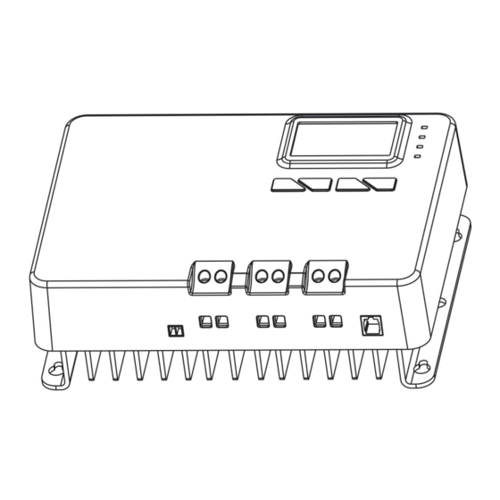
Page 5: Device Diagram
4. Device Diagram Description Description LCD Display Screen DC Load Terminals Function Key ([SET], [UP], [DOWN], [ESC]) RS485 Communication Port External Temperature Sensor Terminal LED Indicator (PV, BAT, LOAD, FAULT) Solar Terminals Installation Mounting Holes Battery Terminals... - Page 6 6. Wire Connection Sequences During installation of your MPPT controller, please follow the order of connection below: Connect the positive battery wire followed by the negative battery wire. Make sure your solar panels are fully covered to prevent electrical shock. Connect the positive solar array output wire followed by the negative solar array output wire.
- Page 7 7. LED Light Signal Interpretation Chart LED Name LED Display Signal Indication Solar Input Not Charging *PV LED is generally off during nighttime. Solar Input Charge Detected Double Flash Single Flash Solar Input Reverse Polarity Steady On MPPT Charge Mode Fast Flash Equalize or Boost Charge Mode Slow Flash...
- Page 8 8. LED Flash Rhythm Chart Flash Indication Description Status Steady LED light on. LED light off. LED light blinks at frequency of Fast Flash 2Hz (twice every second). LED light blinks at frequency of Slow Flash 0.5Hz (once every two seconds). LED light blinks for 0.1 second Single Flash...
- Page 9 9. LCD Display Interface Overview 10. LED Display Interface Display Section Display Layout Charge Status Charge Mode & Parameter Active Functions...
-
Page 10: Status Information
11.Status Information Status Icon Indication Status Description Flowing Solar Power Charging Battery Solar Charge Indication Solar Power Not Charging Battery Flowing DC Load Drawing Power DC Load Indication DC Load Off MPPT Charge Mode Steady On Boost Charge Mode Charge Mode Float Charge Mode Not Charging Setting Charge Voltage... - Page 11 12. Key Functionality Chart Function Key System Mode Input Input Function View Mode Short Press Enter SET mode View Mode View Previous Page Short Press View Mode View Next Page Short Press DC Load On/Off View Mode Short Press (Manual Control Program Only) Function Key System Mode Input...
- Page 12 13. LED Display Rules & Cycles Pre start-up display cycle when the MPPT controller turns on, this usually last several seconds while controller detects operating environment. LED Screen Display Cycle The information pages in the screen will be automatically turning to the next page every 5 ...
- Page 13 Setting Battery Mode Enter SET mode by pressing the Setting key in any view page other than Load Mode. Use the up and down arrow keys to select battery mode, then long press Setting key to save. Abbreviations Battery Types Description Flooded Battery Auto-recognition with default parameters...
- Page 14 Special Cutting Edge Power Lithium Batteries programming: If Cutting Edge Power lithium batteries are installed by the factory, we will program these settings for you. In Lithium mode, short press the Setting key again to cycle through each parameter view. Use the up and down arrow key to adjust parameter value, then long press Setting key to save.
- Page 15 Advanced Battery Settings (Lighting Control mode) Enter Load SET Mode by pressing the Setting key in Load Mode view only. Use the arrow key to cycle through load modes before long pressing SET to save and exit. Short pressing SET will exit without saving. Mode Definition Description...
-
Page 16: Error Code Chart
14. Error Code Chart Code Error Description & Quick Troubleshoot No Error No action needed. Battery voltage is too low. Battery DC load will be turned off until battery re-charges to Over-discharged recovery voltage. Battery voltage has exceeded controller limit. Battery Check battery bank voltage for compatibility with Over-voltage... -
Page 17: Controller Specification
“n” is listed as: if battery system voltage is 12V, n=1; 24V, n=2; 36V, n=3; 48V, n=4. For example, the equalize charge voltage for a 12V FLD (Flooded) battery bank is 14.8V*1=14.8V. The equalizing charge voltage for a 24V FLD (Flooded) battery bank is 14.8V*2=29.6V. Parameter Value CEP400 Model No. 12V/24V Battery System Voltage Auto (FLD/GEL/SLD) -
Page 18: Product Dimension
15. Product Dimension Product Dimension: 245*180*82.5mm / 9.7*7.1*3.3inch Installation Area Dimension: 226*138mm / 8.9*5.4inch Installation Hole Size: φ5mm&φ10mm / φ0.2inch &φ0.4inch Connection Socket Size: 7.5*7.5mm / 0.3*0.3inch...
Need help?
Do you have a question about the CEP400 and is the answer not in the manual?
Questions and answers